
Subscribe to Our Youtube Channel
Related Manuals for Weidmüller UR20-1SM-50W-6DI2DO-P


Summary of Contents for Weidmüller UR20-1SM-50W-6DI2DO-P
- Page 1 Remote-I/O-System u-remote UR20 Stepper motor module UR20-1SM-50W-6DI2DO-P Manual Letʼs connect.
-
Page 2: Table Of Contents
Creating motion profiles with the configuration application Acceleration types Behaviour on interruption of power supply Manufacturer Weidmüller Interface GmbH & Co. KG Klingenbergstraße 16 D-32758 Detmold T +49 5231 14-0 +49 5231 14-292083 Dokument No. 2575290000 www.weidmueller.com Revision 03/March 2020 2575290000/03/03.2020 Manual Stepper motor module UR20-1SM-50W-6DI2DO-P... -
Page 3: About This Documentation
(document No. 2112220000) describes how to information about proper and effective work use the web server application. procedures. All documents are available to download on the Weidmüller Website. 2575290000/03/03.2020 Manual Stepper motor module UR20-1SM-50W-6DI2DO-P... -
Page 4: Standard Data Structure
Available online 2566380000 UR20-FBC-PN-IRT-V2 01.10.01 Japanese 01.05.00 Available online 2659680000 UR20-FBC-PN-ECO 01.00.00 1334910000 UR20-FBC-EC, HW 01.xx.xx 01.11.00 1334910000 UR20-FBC-EC, HW 02.xx.xx 01.12.00 2659690000 UR20-FBC-EC-ECO 01.00.00 1334930000 UR20-FBC-MOD-TCP 02.07.00 2476450000 UR20-FBC-MOD-TCP-V2 02.08.00 2659700000 UR20-FBC-MOD-TCP-ECO 01.00.00 2575290000/03/03.2020 Manual Stepper motor module UR20-1SM-50W-6DI2DO-P... -
Page 5: Safety
Safety Open equipment This chapter includes general safety instructions for hand- ling the Stepper motor module UR20-1SM-50W-6DI2DO-P. u-remote products are open equipment that may only be ins- Specific warning notices for specific tasks and situations are talled and operated in lockable housings, cabinets or electri- given at the appropriate places in the documentation. -
Page 6: Intended Use
If u-remote products are used in potentially explosive atmos- pheres, the following notes are also applicable: The stepper motor module UR20-1SM-50W-6DI2DO-P is an – Staff involved in assembly, installation and operation I/O module from the u-remote series that is designed for use must be qualified to perform safe work on electrical sys- in a u-remote station. -
Page 7: Legal Notice
2 Safety | Legal notice Legal notice The stepper motor module UR20-1SM-50W-6DI2DO-P is CE- compliant in accordance with Directive 2014/30/EU (EMC Directive). It also meets the requirements of the ATEX Direc- tive 2014/34/EU. The results of the measurements according to CISPR 16-2-3... -
Page 8: Module Description
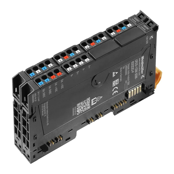
3 Module description Module description UR20-1SM-50W-6DI2DO-P stepper motor module (order no. 2489830000) The UR20-1SM-50W-6DI2DO-P stepper motor module with integrated power amplifier can directly control a two-phase stepper motor. In addition, the module can record up to six binary control signals and control up to two actuators each with maximum 0.5 A. -
Page 9: Device Description
11 Channel status LED 12 Latching hook for latching onto module sides 13 DIN rail foot 14 Type plate Stepper motor modules UR20-1SM-50W-6DI2DO-P components Base modules Elektronic unit Plug-in unit PK1 for digital inputs and outputs Plug-in unit PK2 for stepper motor and power supply 2575290000/03/03.2020... -
Page 10: Connections
8.1 Ext. +VDC 12 V ... 50 V (external) 4.2 GND 0 V (U 8.2 Ext. +VDC 12 V ... 50 V (external) 4.3 DO 1 Digital output 8.3 Ext. 0VDC 0 V (external) 4.4 GND 0 V (U 8.4 Ext. 0VDC 0 V (external) 2575290000/03/03.2020 Manual Stepper motor module UR20-1SM-50W-6DI2DO-P... -
Page 11: Led Indicators
Yellow: Output 0 active Green: external power supply OK Red: external power supply error Yellow: Output 1 active LED indicators UR20-1SM-50W-6DI2DO-P, left, error messages see chapter 7 LED indicators UR20-1SM-50W-6DI2DO-P, right, error messages see chapter 7 2575290000/03/03.2020 Manual Stepper motor module UR20-1SM-50W-6DI2DO-P... -
Page 12: Block Diagram
DI 5 D0 1 D0 0 24VDC OUT DO 1 GND OUT A– B– Ext. +VDC Ext. +VDC Ext. +VDC Ext. +VDC Ext. 0VDC Ext. 0VDC Ext. 0VDC Ext. 0VDC UR20-1SM-50W-6DI2DO-P Block diagram UR20-1SM-50W-6DI2DO-P 2575290000/03/03.2020 Manual Stepper motor module UR20-1SM-50W-6DI2DO-P... -
Page 13: Technical Data
Inputs DI 4 ... DI 5 Number Input type Input characteristics for sensor types 1 and 3 are in accordance with EN 61131-2, suitable incremen- tal encoders, P-switching Input filter Filter time adjustable to 0 or 5 ms 2575290000/03/03.2020 Manual Stepper motor module UR20-1SM-50W-6DI2DO-P... - Page 14 500 mA Short-circuit-proof Protective circuit Constant current with thermal switch-off and automatic restart Response time of the current limiting circuit < 100 μs Individual channel diagnosis Reactionless Can be used with PF-O-xDI-SIL MTTF 53.74 years 2575290000/03/03.2020 Manual Stepper motor module UR20-1SM-50W-6DI2DO-P...
- Page 15 15 g over 11 ms, half sinewave, as per IEC 60068-2-27 Approvals and standards cULus UL 61010 Potentially explosive atmosphere Zone 2 ATEX Directive 2014/34/EU IEC 61000 Explosion protection IEC 60079-0:2012, IEC 60079-15:2010, EN 60079-0:2012, EN 60079-15:2010 IEC 61131-2 2575290000/03/03.2020 Manual Stepper motor module UR20-1SM-50W-6DI2DO-P...
-
Page 16: Derating Curves
3 Module description | Derating curves Derating curves UR20-1SM-50W-6DI2DO-P derating curve with horizontal installation UR20-1SM-50W-6DI2DO-P derating curve with vertical installation 2575290000/03/03.2020 Manual Stepper motor module UR20-1SM-50W-6DI2DO-P... -
Page 17: Adjustable Parameters
3 Module description | Adjustable parameters Adjustable parameters A detailed description for how to parameterise the module is included in Section 5.4. Overview of the editable parameters UR20-1SM-50W-6DI2DO-P Channel Description Options Default Remark Start/Stopp frequency f 5 (0) / 10 (1) / 20 (2) / 50 (3) / 100 (4) / 200 (5) / 500 (6) / 750 (7) / 1000 (8) /... - Page 18 3 Module description | Adjustable parameters Overview of the editable parameters UR20-1SM-50W-6DI2DO-P Channel Description Options Default Remark Encoder function disabled Enc.Pos. in process data (0) / Contouring error monitoring (1) / disabled (2) Homing Stop on Ref.switch 0➝1 (0) / Stop on Ref.switch 1➝0 (1) / Stop on homing bit Stop on Ref.
- Page 19 The input records the signal of a reference switch. The refe- rence point is started up by the stepper motor in a clockwise the other traversing range limit. direction. “Diagnostic alarm” parameter The “diagnostic alarm” parameter activates diagnostic alarms. 2575290000/03/03.2020 Manual Stepper motor module UR20-1SM-50W-6DI2DO-P...
- Page 20 The stepper motor module always evaluates all The output signal is high if the current position of the step- four flanks of the rotary encoder signal. per motor deviates from the target position. The output sig- 2575290000/03/03.2020 Manual Stepper motor module UR20-1SM-50W-6DI2DO-P...
- Page 21 The contouring error is the difference between the current motor position and the rotary encoder position. 0 ... 100 (default: 1) The permissible contouring error is 0 ... 100% of the rotary encoder resolution. 2575290000/03/03.2020 Manual Stepper motor module UR20-1SM-50W-6DI2DO-P...
-
Page 22: Assembly And Installation
▶ In addition, always refer to the complete documentation in the u-remote IP20 manual. ▶ Carry out all work during the installation/removal and replacement of components as described in the u-remote manual. Connecting the bi-polar four-wire stepper motor 2575290000/03/03.2020 Manual Stepper motor module UR20-1SM-50W-6DI2DO-P... -
Page 23: Connecting The Reference Switch
Connecting the limit switch ▶ Connect the stepper motor to connector 7. Limit switches are always evaluated by the step- per motor module as an NC contact. Connecting the bi-polar eight-wire stepper motor (parallel operation) 2575290000/03/03.2020 Manual Stepper motor module UR20-1SM-50W-6DI2DO-P... -
Page 24: Connecting The Incremental Rotary Encoder
Connecting the load ▶ Connect the load to connector 4. Connecting the load Connecting the incremental rotary encoder Connecting signalers for jog mode and tip mode ▶ Connect the switches to connector 2. Connecting switches for jog/tip mode 2575290000/03/03.2020 Manual Stepper motor module UR20-1SM-50W-6DI2DO-P... -
Page 25: Commissioning And Operation
– The u-remote station must be completely assembled and wired. – The control unit and u-remote station must be connected to each other, and a PC/laptop must also be connected. – The power supply must be turned on. 2575290000/03/03.2020 Manual Stepper motor module UR20-1SM-50W-6DI2DO-P... -
Page 26: Parameterising The Module For The Drive System
The stepper motor module references with start/ stop frequency. Make sure that you select a start/ stop frequency that is low enough to prevent the lever of the reference switch from being driven over. 2575290000/03/03.2020 Manual Stepper motor module UR20-1SM-50W-6DI2DO-P... - Page 27 ▶ Set the “encoder function” parameter to “contouring error monitoring”. ▶ Set the “full steps stepper motor/rev.” parameter to the number of steps for the stepper motor. ▶ Set the “contouring error” parameter to the maximum permissible contouring error. 2575290000/03/03.2020 Manual Stepper motor module UR20-1SM-50W-6DI2DO-P...
-
Page 28: Controlling The Drive System
1. You can then set the current position of the stepper motor or the rotary encoder. If no reference switch is found during referencing, the run ends at an end stop. 2575290000/03/03.2020 Manual Stepper motor module UR20-1SM-50W-6DI2DO-P... - Page 29 “moving“ is set to 1. “Feedback register page num- ber“ shows the number of the current register page. “Feed- back data set number“ shows the number of the current data set. 2575290000/03/03.2020 Manual Stepper motor module UR20-1SM-50W-6DI2DO-P...
-
Page 30: Register Communication Via Process Data
If you deactivate the signaler while the limit switch is still activated, you must repeat the process. After you have released the end position, you must perform a reference run. 2575290000/03/03.2020 Manual Stepper motor module UR20-1SM-50W-6DI2DO-P... - Page 31 1) Reserved for subsequent firmware releases write into the register. ▶ Set “Read or write register“to 1 for writing access. ▶ Set “Read or write EEPROM“ to 0. ▶ To initiate the register access, set “Register access request“ to 1. 2575290000/03/03.2020 Manual Stepper motor module UR20-1SM-50W-6DI2DO-P...
-
Page 32: Creating Motion Profiles With The Configuration Application
“con- UR20-FBC-EC, HW 01.xx.xx 01.08.00 figure drive system”. UR20-FBC-MOD-TCP-V2 02.06.00 ▶ Click on “configure drive system”. UR20-FBC-MOD-TCP 02.06.00 UR20-FBC-EIP, HW 02.xx.xx 02.07.00 UR20-FBC-EIP, HW 01.xx.xx 01.07.00 UR20-FBC-DN 01.06.00 UR20-FBC-CAN 01.06.00 UR20-FBC-PL 01.06.00 2575290000/03/03.2020 Manual Stepper motor module UR20-1SM-50W-6DI2DO-P... - Page 33 Diameter of the pitch circle circumference Positions per Number of discrete positions per revoluti- Rotary table revolution on in the selected unit ▶ Check the automatically calculated values under “sum- mary” and adjust your entries if necessary. 2575290000/03/03.2020 Manual Stepper motor module UR20-1SM-50W-6DI2DO-P...
- Page 34 ▶ Under “preview of the registers to be written”, check the motion register setup. ▶ Click on “export” to export the current register setup. The current motion register setup is saved on your computer as “configuration_UR20-1SM-50W-6DI-2DO.json”. 2575290000/03/03.2020 Manual Stepper motor module UR20-1SM-50W-6DI2DO-P...
-
Page 35: Acceleration Types
Jerk (j), velocity (v) and stroke (s) on contant acceleration (a) pared to constant acceleration. With the same maximum ac- During acceleration and braking procedures, the acceleration celeration, the travel time is increased compared to constant is constant. acceleration. 2575290000/03/03.2020 Manual Stepper motor module UR20-1SM-50W-6DI2DO-P... - Page 36 During acceleration and braking procedures, the acceleration describes a eine sin² curve. The jerk‘s harmonics are reduced compared to linear acceleration. The travel time on optimal acceleration corresponds to the travel time on linear acceler- ation. 2575290000/03/03.2020 Manual Stepper motor module UR20-1SM-50W-6DI2DO-P...
-
Page 37: Behaviour On Interruption Of Power Supply
The module reports an error. The active motion is cancelled. 3. Set the Bit SM_MOV “moving“ (PDA 9.1) to 0. 4. Acknowledge the error status with Bit SM_QUITT (PDA 9.6) “Acknowledge error motor driver“. Travel commands are now possible again. 2575290000/03/03.2020 Manual Stepper motor module UR20-1SM-50W-6DI2DO-P... -
Page 38: Process Data
Moving sets taken over IX10.5 Register write acknowledge IX10.6 Register write accepted IX10.7 Register read abort IB11 Byte IX11.0 ... IX11.7 Register read adress IB12 ... IB15 Double Word IX12.0 ... IX15.7 Register read data 1) Reserved for future firmware versions 2575290000/03/03.2020 Manual Stepper motor module UR20-1SM-50W-6DI2DO-P... -
Page 39: Process Output Data
Control bit write more moving sets QX10.5 – QX10.6 Register read or write QX10.7 Register access request QB11 Byte QX11.0 ... QX11.7 Register write adress QB12 ... QB15 Double Word QX12.0 ... QX15.7 Register write data 1) Reserved for future firmware versions 2575290000/03/03.2020 Manual Stepper motor module UR20-1SM-50W-6DI2DO-P... -
Page 40: Data Width, Dependent On The Coupler Used
6 Process data | Data width, dependent on the coupler used Data width, dependent on the coupler used Data width of UR20-1SM-50W-6DI2DO-P, dependent on the coupler used Order no. Coupler Configuration Parameters Diagnostics Process data Input Output Byte Byte Byte Byte... -
Page 41: Diagnostics And Troubleshooting
Number of channels 0 ... 7 Reserved Error at channel 8 Channel error 8 Error at channel 9 2 ... 7 Reserved 9 ... 10 Reserved Channel 0 error 0 ... 7 Reserved Channel 7 error 2575290000/03/03.2020 Manual Stepper motor module UR20-1SM-50W-6DI2DO-P... -
Page 42: Led Indicators And Troubleshooting
– Observe derating curves in the technical datan – Thermal overload at the motor driver Green: external power supply OK – Red: external power supply error – Check external supply voltage – Voltage levels exceed allowed limits 2575290000/03/03.2020 Manual Stepper motor module UR20-1SM-50W-6DI2DO-P... -
Page 43: Disassembly And Disposal
▶ Slide the module group to the right and remove it from the DIN rail. ▶ Repeat the above procedure for all remaining modules/ module groups. ▶ Please observe the instructions for proper disposal. 2575290000/03/03.2020 Manual Stepper motor module UR20-1SM-50W-6DI2DO-P... - Page 44 Weidmüller – Your Partner in Industrial Connectivity As experienced experts we support our customers and partners around the world with products, solutions and services in the industrial environment of power, signal and data. We are at home in their industries and markets and know the technological challenges of tomorrow.
Need help?
Do you have a question about the UR20-1SM-50W-6DI2DO-P and is the answer not in the manual?
Questions and answers