
Related Manuals for dunkermotoren BG 65x75 MI


Summarization of Contents
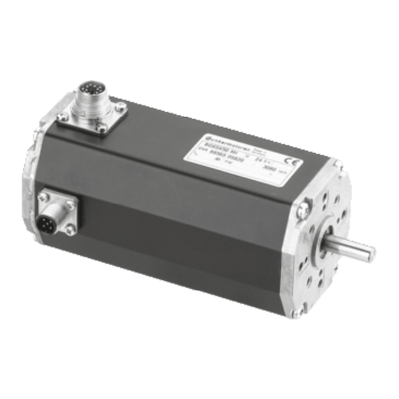
General description
Motor range BG 65 MI
Describes the BG 65 MI series of brushless DC motors with integral motion controller and CAN interface.
Explanations of terms used
Defines key technical terms and acronyms used in the manual for clarity and understanding.
Proper use
Outlines the intended applications and conditions for using the BG 65 MI motor in machines and plants.
Technical data, accessories
Electrical data
Details electrical specifications like voltage, current, speed range, and fuse requirements.
Mechanical data
Provides mechanical specifications including temperature, humidity, protection degree, and connector types.
Motor installation drawing
Illustrates the physical dimensions and mounting points for motor installation.
Motor BG 65x25 MI
Presents the specific technical data for the BG 65x25 MI motor variant.
Motor BG 65x50 MI
Presents the specific technical data for the BG 65x50 MI motor variant.
Motor BG 65x75 MI
Presents the specific technical data for the BG 65x75 MI motor variant.
Optional attachments
Describes optional accessories like encoders, gearboxes, and brakes available for the motors.
Protective functions
Ballast circuit
Explains the ballast circuit for managing braking energy and preventing overvoltage.
Over-temperature cut-off
Details the motor's protection against overheating, including error codes and deactivation.
Current limitation
Describes parameters for limiting current to protect against overload and blocking.
Installation / terminal assignment
Mechanical assembly
Guides on securely mounting the drive and handling connectors without damage.
Electro-magnetic compatibility
Addresses EMC aspects, potential interference, and required measures for smooth operation.
Protective earth connection
Explains the importance of earthing the motor housing for ESD protection.
Motor power supply and signal interface supply
Details the 12-pin motor connector for power and 24V supply to control electronics.
Schematic circuit of the digital outputs
Provides a schematic of the digital output circuits and their typical usage.
Schematic circuit of the digital inputs
Provides a schematic of the digital input circuits and their typical usage.
Maximum cable length and power supply
Specifies maximum cable lengths and considerations for power supply configurations.
CAN field bus connection
Details the motor plug and pin assignment for CAN field bus communication.
Commissioning
Schematic circuit for power supply controller/ motor BG65 MI
Shows the schematic for power supply and soft start resistor for controller/motor connection.
Maintenance & Service
Maintenance, taking out of service and disposal
Covers maintenance needs, safe removal from service, and proper disposal procedures.
Service & Support
Provides contact information for sales, key account managers, and support departments.
Scope of delivery and accessories
Lists the standard scope of delivery and available accessories for the motor.
Download PDF-Data
Directs users to download PDF manuals and data from the company website.
Need help?
Do you have a question about the BG 65x75 MI and is the answer not in the manual?
Questions and answers