
Related Manuals for dunkermotoren BG 65 SI


Summary of Contents for dunkermotoren BG 65 SI
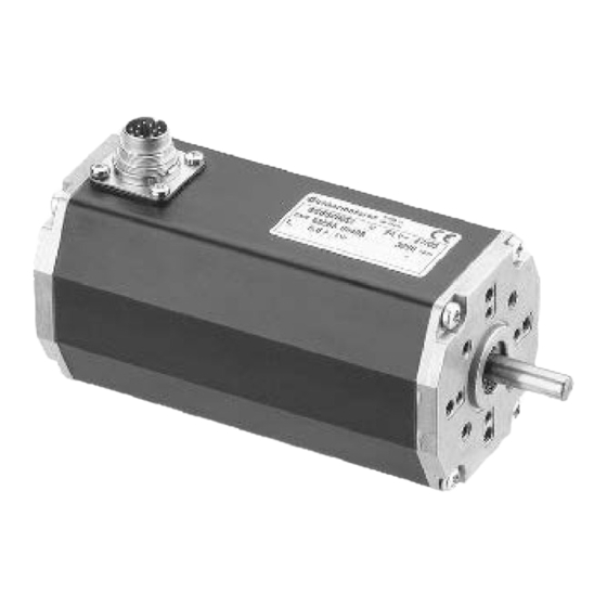
- Page 1 Instruction Manual / Betriebsanleitung BLDC motor with integrated speed controller Bürstenloser DC-Motor mit integriertem Drehzahlregler BG 65 SI Edition / Ausgabe (05/2010)
-
Page 2: Table Of Contents
Spannungsversorgung 8 Connection schematic 8 Anschlussschema 8.1 Schematic circuit for power supply 8.1 Prinzipschaltbild Spannungs- controller/ motor BG65 SI versorgung Regler/ Motor BG65 SI Instruction Manual/Betriebsanleitung BG 65 SI, Version: 1.3 en_de © 2010 Dunkermotoren GmbH; D-79848 Bonndorf; Germany... - Page 3 10.4 Scope of delivery and accessories 10.4 Lieferumfang und Zubehör 10.5 Download PDF-Data 10.5 Download PDF-Daten 11 Appendix 11 Anhang A) CE-declaration of the manufacturer A) CE-Herstellererklärung Instruction Manual/Betriebsanleitung BG 65 SI, Version: 1.3 en_de © 2010 Dunkermotoren GmbH; D-79848 Bonndorf; Germany...
-
Page 4: About This Document
Einstellungen und helfen certain settings and help you use the Ihnen, den optimalen Nutzen aus dem device to the best possible effect. Gerät zu ziehen. NOTICE HINWEIS Instruction Manual/Betriebsanleitung BG 65 SI, Version: 1.3 en_de © 2010 Dunkermotoren GmbH; D-79848 Bonndorf; Germany... -
Page 5: General Description
3.1 Motor series BG 65 SI 3.1 Motorbaureihe BG 65 SI The motor type BG 65 SI represents EC-motors Bei der Motorbaureihe BG 65 SI handelt es sich um (brushless DC motor) with an integrated speed control EC-Motoren (bürstenlose DC-Motoren) mit ange- electronic for 4-quadrant operation. -
Page 6: Explanations Of Terms Used
3.3 Bestimmungsgemäße Verwendung 3.3 Proper use - Der Motor BG 65 SI sind Zulieferteile und dür- - The BG 65 SI motor is a supplied part and may fen in der beschriebenen Konfiguration in Maschinen be installed into (industrial) machinery and equip- und Anlagen eingesetzt werden (industrieller Be- ment in the described configuration. -
Page 7: Standards And Guidelines
EMC standards. The product Sicherheit und EMV entspricht. Das Produkt darf in may be sold and used within the European Union. der Europäischen Union vertrieben und eingesetzt werden. Instruction Manual/Betriebsanleitung BG 65 SI, Version: 1.3 en_de © 2010 Dunkermotoren GmbH; D-79848 Bonndorf; Germany... -
Page 8: Safety Instructions
► z.B. (See technical data) (Siehe technische Daten) Transport the drive under storage Transportieren Sie die Antriebe unter conditions Lagerbedingungen: protection against shock ► stoßgeschützt ► Instruction Manual/Betriebsanleitung BG 65 SI, Version: 1.3 en_de © 2010 Dunkermotoren GmbH; D-79848 Bonndorf; Germany... -
Page 9: Technical Data, Accessories
Additional Drehgeber und unbelasteten digitalen Ausgängen. Eventuell components connected to the outputs increase the current an den Ausgängen angeschlossene Komponenten erhöhen consumption. den Strombedarf entsprechend. Instruction Manual/Betriebsanleitung BG 65 SI, Version: 1.3 en_de © 2010 Dunkermotoren GmbH; D-79848 Bonndorf; Germany... -
Page 10: Mechanical Data
Antrieb in einer Umgebung entsprechend IP54 einge- setzt werden. ***) Weitere Informationen finden Sie im Abschnitt An- ***) Please see the pin diagram for further information. schlussbelegung. 5.3 Motormasszeichnung 5.3 Dimensions Instruction Manual/Betriebsanleitung BG 65 SI, Version: 1.3 en_de © 2010 Dunkermotoren GmbH; D-79848 Bonndorf; Germany... -
Page 11: Motor Bg 65X25 Si
Stahlplatte der Größe 105 x 105 x 10 mm (Angabe in steel plate with the dimensions 105x105x10mm (data Klammern). inbrackets). **) Die Steckerausführung ist Standard. **) The connector version is standard. Instruction Manual/Betriebsanleitung BG 65 SI, Version: 1.3 en_de © 2010 Dunkermotoren GmbH; D-79848 Bonndorf; Germany... -
Page 12: Accessories
Brushless DC motors in the BG range can be fitted with Bürstenlose Gleichstrommotoren der Baureihe BG a power-off or a power-on brake as an option. können optional mit angebauten Ruhe- oder Arbeits- strombremsen ausgerüstet werden. Instruction Manual/Betriebsanleitung BG 65 SI, Version: 1.3 en_de © 2010 Dunkermotoren GmbH; D-79848 Bonndorf; Germany... -
Page 13: Protective Functions
The error can be confirmed after the fall below the dem Unterschreiten von 84°C wieder quittiert werden. temperature limit of 84°C. The motor can be started Der Motor ist dann wieder fahrbereit. again. Instruction Manual/Betriebsanleitung BG 65 SI, Version: 1.3 en_de © 2010 Dunkermotoren GmbH; D-79848 Bonndorf; Germany... -
Page 14: Installation / Terminal Assignment
Die Motorabtriebswelle darf mit maximal 90 bzw. 130 N gears. radial oder axial belastet werden. Bei Getriebmotoren sind die entsprechenden Daten der Dokumentation zum Getriebe zu entnehmen. Instruction Manual/Betriebsanleitung BG 65 SI, Version: 1.3 en_de © 2010 Dunkermotoren GmbH; D-79848 Bonndorf; Germany... -
Page 15: Electromechanical Compatibility
Electromagnetic radiated interferences occur in the Beim Antrieb BG 65 SI und bei der Maschine, in drive BG 65 SI and the machine in which the drive welche der Antrieb eingebaut wird, entstehen elek- is installed. Should no suitable protective measures tromagnetische Störstrahlungen. -
Page 16: Connection Alternatives
The 12-pin drive connector serves for the motor power Der 12-polige Antriebsstecker dient zur Leistungsver- supply and the electronic supply. sorgung des Antriebs und zur Elektronikversorgung. Instruction Manual/Betriebsanleitung BG 65 SI, Version: 1.3 en_de © 2010 Dunkermotoren GmbH; D-79848 Bonndorf; Germany... -
Page 17: Connection 24 V-Motors
7.5.2 Anschluss 42 V-Motoren Signale / Signals (E/A): Versorgung / Supply: Leistung / Power Logik / Logic +24 V DC +42 V DC GND (0V) GND (0V) Instruction Manual/Betriebsanleitung BG 65 SI, Version: 1.3 en_de © 2010 Dunkermotoren GmbH; D-79848 Bonndorf; Germany... -
Page 18: Connection Via 12-Pin Connector For 24-Motors
(*) Litzenfarben beziehen sich auf Standard An- of Dunkermotoren. schlussleitungen von Dunkermotoren. **) See chapter 8.3 for further functions. **) Weitere Funktionen von IN3 und IN4 siehe Punkt 8.3. Instruction Manual/Betriebsanleitung BG 65 SI, Version: 1.3 en_de © 2010 Dunkermotoren GmbH; D-79848 Bonndorf; Germany... -
Page 19: Connection Via 12-Pin Connector For 42 V-Motors
= fault OK-Meldung OK-Message (*) Litzenfarben beziehen sich auf Standard An- (*) Lead colours refers to standard connection cables schlussleitungen von Dunkermotoren. of Dunkermotoren. Instruction Manual/Betriebsanleitung BG 65 SI, Version: 1.3 en_de © 2010 Dunkermotoren GmbH; D-79848 Bonndorf; Germany... -
Page 20: Schematic Circuit Of The Digital Outputs
Gegenstecker mit Anschlußleitung ( bitte mitbestellen): Adequate connector cables with different standard Für die Motoren BG 65 SI mit seitlichem Anschluss- lengths are available for the motors BG 65 SI with stecker (12-polig) stehen entsprechende geschirmte connector plugs (12-pole). They are shielded and und schleppkettentaugliche, fertig konfektionierte dragchain capable. -
Page 21: Maximale Kabellängen Und Spannungsversorgung
Kabellänge* Kabel nung [V] Kabellänge BG65 (SI, PI, CI, MI) 21,6 27573 35530 27573 35532 24,0 * Can be ordered at Dunkermotoren/ bestellbar bei Dunkermotoren Instruction Manual/Betriebsanleitung BG 65 SI, Version: 1.3 en_de © 2010 Dunkermotoren GmbH; D-79848 Bonndorf; Germany... - Page 22 Spannungsquellen, sind the following cable lengths are available: folgende Leitungslängen lieferbar: Length Länge 1.5 m 1,5 m 10 m 10 m Instruction Manual/Betriebsanleitung BG 65 SI, Version: 1.3 en_de © 2010 Dunkermotoren GmbH; D-79848 Bonndorf; Germany...
-
Page 23: Connection Schematic
VORSICHT Consequence: Die Folge: Destroying of the integrated electronics Zerstörung der integrierten Elektronik possible. möglich. Auf richtige Polarität achten! ► Check the right polarity ► Instruction Manual/Betriebsanleitung BG 65 SI, Version: 1.3 en_de © 2010 Dunkermotoren GmbH; D-79848 Bonndorf; Germany... -
Page 24: Prinzipschaltbild Spannungs- Versorgung Regler/ Motor Bg65 Si
Prinzipschaltbilder für die Spannungsversorgung (BG 45, BG65, BG75). (Regler/ Motoren) der entsprechenden Motorvarianten (BG 45, 65, BG75) in den jeweiligen Bedienungsanlei- tungen beachtet werden. Instruction Manual/Betriebsanleitung BG 65 SI, Version: 1.3 en_de © 2010 Dunkermotoren GmbH; D-79848 Bonndorf; Germany... -
Page 25: Operation Hints
(IN1 = IN2 = 0) at activated supply voltage. nicht einschalten. Zum Rücksetzen (Quittierung) muss der Motor bei eingeschalteter Versorgungsspannung in den Zustand „AUS“ (IN1 = IN2 = 0) versetzt werden. Instruction Manual/Betriebsanleitung BG 65 SI, Version: 1.3 en_de © 2010 Dunkermotoren GmbH; D-79848 Bonndorf; Germany... -
Page 26: Function Of The Digital Inputs In1
0 entspricht einem Eingangspegel von 0 ... 6 V 1 complies with an input level of 7 ... 24 V 1 entspricht einem Eingangspegel von 7 ... 24 V Instruction Manual/Betriebsanleitung BG 65 SI, Version: 1.3 en_de © 2010 Dunkermotoren GmbH; D-79848 Bonndorf; Germany... -
Page 27: Teaching Of Fixed Speeds
Trennen der Versorgungsspannung neu zu starten. To teach the second fixed speed, repeat this proce Zum Teachen der zweiten festen Geschwindigkeit dure. ist der Vorgang zu wiederholen. Instruction Manual/Betriebsanleitung BG 65 SI, Version: 1.3 en_de © 2010 Dunkermotoren GmbH; D-79848 Bonndorf; Germany... -
Page 28: Teaching Of Ramps
For clarification, some values are presented in Sollwertsteller dem Drehzahlregler vorgeschaltet. Zur table form: Verdeutlichung sind einige Werte tabellarisch darge- (see next page) stellt: (siehe nächste Seite) Instruction Manual/Betriebsanleitung BG 65 SI, Version: 1.3 en_de © 2010 Dunkermotoren GmbH; D-79848 Bonndorf; Germany... - Page 29 Trennen der Versorgungsspannung neu zu starten. To teach the second ramp, repeat this procedure. Zum Teachen der zweiten Rampe ist der Vorgang zu wiederholen. Instruction Manual/Betriebsanleitung BG 65 SI, Version: 1.3 en_de © 2010 Dunkermotoren GmbH; D-79848 Bonndorf; Germany...
-
Page 30: Function Of The Pulse Output Out1
Der Ausgang ist als PNP-Transistor 24 V-plusschal- switching, with a max. permitted current strain of 10 mA. tend mit einer max. zulässigen Strombebelastung von 10 mA ausgeführt. Instruction Manual/Betriebsanleitung BG 65 SI, Version: 1.3 en_de © 2010 Dunkermotoren GmbH; D-79848 Bonndorf; Germany... -
Page 31: Protective Functions And Fault Output Out3
84 °C ein Under- Soft- 16,5 V off, Unter- Soft- 16,5 V aus, voltage ware 18,5 V on spannung ware 18,5 V ein Instruction Manual/Betriebsanleitung BG 65 SI, Version: 1.3 en_de © 2010 Dunkermotoren GmbH; D-79848 Bonndorf; Germany... -
Page 32: Function Of The Analogue Input Ai+/Ai
Erhöhung der Drehzahl. Note: Hinweis: A not connected analogue input equals 0 rpm. Ein nicht angeschlossener Analogeingang entspricht einer Drehzahl von 0. Instruction Manual/Betriebsanleitung BG 65 SI, Version: 1.3 en_de © 2010 Dunkermotoren GmbH; D-79848 Bonndorf; Germany... -
Page 33: Motors With Additional Brake
(z.B. Typ 1N4004 oder vergleichbar) Assemble the recovery diode according to following Die Freilaufdiode ist gemäß nachfolgender Skizze drawing: einzubauen: Figure 4 Abbildung 4 Figure 5: Abbildung 5: Instruction Manual/Betriebsanleitung BG 65 SI, Version: 1.3 en_de © 2010 Dunkermotoren GmbH; D-79848 Bonndorf; Germany... -
Page 34: Maintenance & Service
Dun- Stör-fall direkt an uns und lassen Sie Reparaturen am kermotoren. Antrieb nur von Dunkermotoren durchführen. Instruction Manual/Betriebsanleitung BG 65 SI, Version: 1.3 en_de © 2010 Dunkermotoren GmbH; D-79848 Bonndorf; Germany... -
Page 35: Service & Support
E-Mail: info@dunkermotoren.de E-Mail: info@dunkermotoren.de 10.4 Scope of delivery and accessories 10.4 Lieferumfang und Zubehör As quoted Wie angeboten 10.5 Download PDF-Data 10.5 Download PDF-Daten www.dunkermotoren.de www.dunkermotoren.de Instruction Manual/Betriebsanleitung BG 65 SI, Version: 1.3 en_de © 2010 Dunkermotoren GmbH; D-79848 Bonndorf; Germany... -
Page 36: Appendix
EC- Machine regulations. Maschinen-Richtlinie entspricht. Bonndorf, den 28.11.05 K. Pfendler Bonndorf, den 28.11.05 K. Pfendler (Leiter Entwicklung/Konstruktion) (Director Development / Construction) Instruction Manual/Betriebsanleitung BG 65 SI, Version: 1.3 en_de © 2010 Dunkermotoren GmbH; D-79848 Bonndorf; Germany... - Page 37 Notes Notizen...
- Page 38 Notes Notizen...
Need help?
Do you have a question about the BG 65 SI and is the answer not in the manual?
Questions and answers