
Related Manuals for dunkermotoren BG 65x50 MI


Summary of Contents for dunkermotoren BG 65x50 MI
- Page 1 Instruction Manual / Betriebsanleitung Motor with freely programmable motion controller integrated Motor mit integriertem frei programmierbaren Motioncontroller BG 65 MI Edition / Ausgabe (05/2010)
-
Page 2: Table Of Contents
Entsorgung 10.2 Service & Support 10.2 Service & Support 10.3 Scope of delivery and accessories 10.3 Lieferumfang und Zubehör 10.4 Download PDF-Data 10.4 Download PDF-Daten Instruction Manual/Betriebsanleitung BG 65 MI, Version: 1.3 en_de © 2010 Dunkermotoren GmbH; D-79848 Bonndorf; Germany... - Page 3 Safety instructions Sicherheitshinweise Read and understand this manual carefully before instal- Lesen Sie diese Betriebsanleitung vor Anschluss und ling and operating the motor and follow the instructions to Inbetriebnahme des Motors. Befolgen Sie die Anwei- ensure a flawless operation. Failure to observe this rule sungen, um einen störungsfreien Betrieb zu gewährlei- will invalidate all liability and warranty.
-
Page 4: Contents
Bent pins can cause a short circuit and Umgebogene Pins können den Antrieb NOTICE HINWEIS destroy the drive effects. durch Kurzschluss zerstören. » During installation, ensure that » Beschädigen Sie keine Steckver- connectors are not damaged binder » Damaged connectors must be »... -
Page 5: About This Document
Einstellungen und helfen certain settings and help you use the Ihnen, den optimalen Nutzen aus dem device to the best possible effect. Gerät zu ziehen. NOTICE HINWEIS Instruction Manual/Betriebsanleitung BG 65 MI, Version: 1.3 en_de © 2010 Dunkermotoren GmbH; D-79848 Bonndorf; Germany... -
Page 6: General Description
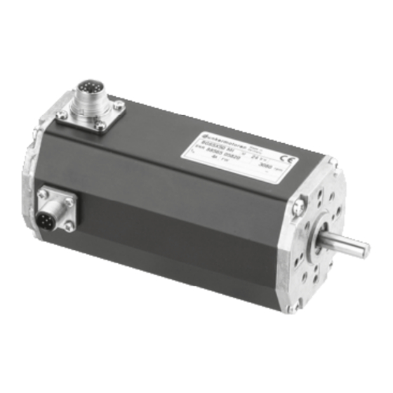
Motor CAN-Stecker CAN connector Kugelgelagerte Motorabtriebswelle Hallsensoren (integriert) optional angebautes Getriebe Hall sensors integrated Motor shaft supported on ball bearings optional gearboxes mounted here Instruction Manual/Betriebsanleitung BG 65 MI, Version: 1.3 en_de © 2010 Dunkermotoren GmbH; D-79848 Bonndorf; Germany... -
Page 7: Explanations Of Terms Used
Auch “Current Mode”, Dreh- Torque mode Torque Mode to as “Current Mode” momentregelung Trajectory Sequence of motions Trajektorie Bewegungsablauf Velocity mode Speed regulation Velocity Mode Drehzahlregelung Instruction Manual/Betriebsanleitung BG 65 MI, Version: 1.3 en_de © 2010 Dunkermotoren GmbH; D-79848 Bonndorf; Germany... -
Page 8: Proper Use
- The drive may only be put into service after the complete system has been installed with due des Gesamtsystems in Betrieb genommen werden. attenti on to EMC aspects. Instruction Manual/Betriebsanleitung BG 65 MI, Version: 1.3 en_de © 2010 Dunkermotoren GmbH; D-79848 Bonndorf; Germany... -
Page 9: Safety Instructions
► z.B. (See technical data) (Siehe technische Daten) Transport the drive under storage Transportieren Sie die Antriebe unter conditions Lagerbedingungen: protection against shock ► stoßgeschützt ► Instruction Manual/Betriebsanleitung BG 65 MI, Version: 1.3 en_de © 2010 Dunkermotoren GmbH; D-79848 Bonndorf; Germany... -
Page 10: Technical Data, Accessories
Antrieb in einer Umgebung entsprechend IP65 einge- IP65. setzt werden. Instruction Manual/Betriebsanleitung BG 65 MI, Version: 1.3 en_de © 2010 Dunkermotoren GmbH; D-79848 Bonndorf; Germany... -
Page 11: Motor Installation Drawing
65x65 mm, 115 mm long Dimensions (without (without incremental Abmessungen (ohne 65x65 mm, 115 mm lang connector) encoder) Stecker) (ohne Inkrementalgeber) Weight Ca. 950 g Gewicht ca. 950 g Instruction Manual/Betriebsanleitung BG 65 MI, Version: 1.3 en_de © 2010 Dunkermotoren GmbH; D-79848 Bonndorf; Germany... -
Page 12: Motor Bg 65X50 Mi
105 x 105 x 10 gemessen bei Anbringung einer thermisch leitenden mm attached to the motor. Stahlplatte der Größe 105 x 105 x 10 mm aufgeführt. Instruction Manual/Betriebsanleitung BG 65 MI, Version: 1.3 en_de © 2010 Dunkermotoren GmbH; D-79848 Bonndorf; Germany... -
Page 13: Optional Attachments
Among other following types of operation are possible: - Current/torque mode - Current/torque mode - Velocity mode - Velocity mode - Position mode - Position mode - SVEL mode - SVEL mode Instruction Manual/Betriebsanleitung BG 65 MI, Version: 1.3 en_de © 2010 Dunkermotoren GmbH; D-79848 Bonndorf; Germany... -
Page 14: Protective Functions
Das Verhalten nach der Fehlerauslösung kann über nagement“ and „event-handling“ das Bremsmanagement und den Event-Händler (active braking, ignore of the mistake). definiert werden (aktives Bremsen, ignorieren des Fehlers). Instruction Manual/Betriebsanleitung BG 65 MI, Version: 1.3 en_de © 2010 Dunkermotoren GmbH; D-79848 Bonndorf; Germany... -
Page 15: Current Limitation
Stromparameter dynamisch vom Mastersystem der parameters can be dynamically adapted by the master Antriebssituation angepaßt werden. system to suit the drive situation. Instruction Manual/Betriebsanleitung BG 65 MI, Version: 1.3 en_de © 2010 Dunkermotoren GmbH; D-79848 Bonndorf; Germany... -
Page 16: Installation/ Terminal Assignment
• This cable must be connected to the flange with a screw. • Hierzu wird das Kabel mit einer Schraube im Flansch • Please avoid touching the connector pins befestigt. • Bitte die Steckerpins nicht berühren Instruction Manual/Betriebsanleitung BG 65 MI, Version: 1.3 en_de © 2010 Dunkermotoren GmbH; D-79848 Bonndorf; Germany... -
Page 17: Motor Power Supply And Signal Interface Supply
Der 12-polige Motorstecker dient zur Spannungsver- sorgung des Motors und zur Spannungsversorgung tor and a 24V supply for the control electronics. und Logikversorgung mit 24 V für die Regelelektronik. Instruction Manual/Betriebsanleitung BG 65 MI, Version: 1.3 en_de © 2010 Dunkermotoren GmbH; D-79848 Bonndorf; Germany... - Page 18 OUT2 weiß OUT2 gang OUT2 (*) Lead colours refers to standard connection cables (*) Litzenfarben beziehen sich auf Standard An- of Dunkermotoren. schlussleitungen von Dunkermotoren. Instruction Manual/Betriebsanleitung BG 65 MI, Version: 1.3 en_de © 2010 Dunkermotoren GmbH; D-79848 Bonndorf; Germany...
-
Page 19: Schematic Circuit Of The Digital Outputs
Fehlfunktion durch gelöste Litzen an solder point possible den Lötstellen möglich ► Don‘t turn the connector more than +/- 45° ► Stecker maximal um +/- 45° verdrehen! Instruction Manual/Betriebsanleitung BG 65 MI, Version: 1.3 en_de © 2010 Dunkermotoren GmbH; D-79848 Bonndorf; Germany... - Page 20 Standard (angled positions not adjustable) Standard (Winkelposition nicht einstellbar) Option (angeld position adjustable) Option (Winkelposition einstellbar) Instruction Manual/Betriebsanleitung BG 65 MI, Version: 1.3 en_de © 2010 Dunkermotoren GmbH; D-79848 Bonndorf; Germany...
-
Page 21: Maximum Cable Length And Power Supply
21,6 27573 35530 27573 35532 24,0 * Can be ordered at Dunkermotoren/ bestellbar bei Dunkermotoren If the supply of power and logic electronic Erfolgt die Versorgung von Leistungs- und is procceded by separate power sources, Logikteil durch getrennte Spannungsquellen, sind the following cable lengths are available: folgende Leitungslängen lieferbar:... -
Page 22: Can Field Bus Connection
Fa. Lumberg, Typ 0935 253 103 Lumberg, Type 0935 253 103 Leitungslänge Bestellnummer Cable length Order number 16597 57014 16597 57014 16597 57016 16597 57016 Instruction Manual/Betriebsanleitung BG 65 MI, Version: 1.3 en_de © 2010 Dunkermotoren GmbH; D-79848 Bonndorf; Germany... -
Page 23: Commissioning
All drives of the series BG 65 MI are applied for cu- Da die Antriebe der Baureihe BG 65 MI für Kundenpro- stomer projects, this requires a special commissioning jekte von Dunkermotoren appliziert werden, muss für manual depending on the customzid programming of die Inbetriebnahme in Abhänigkeit der kundenspezi- fischen Programmierung eine spezielle Bedieneinwei- the drives. -
Page 24: Schematic Circuit For Power Supply Controller/ Motor Bg65 Mi
Prinzipschaltbilder für die Spannungsversorgung (BG 45, BG65, BG75). (Regler/ Motoren) der entsprechenden Motorvarianten (BG 45, 65, BG75) in den jeweiligen Bedienungsanlei- tungen beachtet werden. Instruction Manual/Betriebsanleitung BG 65 MI, Version: 1.3 en_de © 2010 Dunkermotoren GmbH; D-79848 Bonndorf; Germany... -
Page 25: Maintenance & Service
- Ihre zuständige Vertretung - Your local Dunkermotoren sales outlet - Ihr zuständiger Dunkermotoren Key Account - Your local Dunkermotoren key account manager Manager - Our hardware support department - Unsere Supportabteilung für Hardware - Our software support department - Unsere Supportabteilung für Software... -
Page 26: Scope Of Delivery And Accessories
10.3 Scope of delivery and accessories 10.3 Lieferumfang und Zubehör As quoted Wie angeboten 10.4 Download PDF-Data 10.4 Download PDF-Daten www.dunkermotoren.de www.dunkermotoren.de Instruction Manual/Betriebsanleitung BG 65 MI, Version: 1.3 en_de © 2010 Dunkermotoren GmbH; D-79848 Bonndorf; Germany... - Page 27 Notes Notizen Instruction Manual/Betriebsanleitung BG 65 MI, Version: 1.3 en_de © 2010 Dunkermotoren GmbH; D-79848 Bonndorf; Germany...
- Page 28 Notes Notizen Instruction Manual/Betriebsanleitung BG 65 MI, Version: 1.3 en_de © 2010 Dunkermotoren GmbH; D-79848 Bonndorf; Germany...
- Page 29 Notes Notizen Instruction Manual/Betriebsanleitung BG 65 MI, Version: 1.3 en_de © 2010 Dunkermotoren GmbH; D-79848 Bonndorf; Germany...
Need help?
Do you have a question about the BG 65x50 MI and is the answer not in the manual?
Questions and answers