Advertisement
Quick Links
INSTALLATION MANUAL
FOR THE
KC40T KC130TM
SOLAR PHOTOVOLTAIC POWER MODULES
Please read this manual carefully before installing the modules.
1. INTRODUCTION
As the world leader in development and application of high technology
ceramic/silica materials, Kyocera offers a wide range of highly efficient
and reliable crystalline silicon solar photovoltaic (PV) power modules.
Kyocera began to extensively research PV technology in 1975 and
commenced manufacturing operations in 1978. Since then, Kyocera has
supplied millions of cells and modules throughout the world. With years of
experience and state-of-the-art technology, Kyocera provides the highest
quality PV power modules in a range of sizes designed to meet the
requirements of the most demanding energy and power users worldwide.
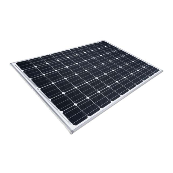
2. POWER MODULES
Kyocera power modules consist of a series of electrically interconnected
crystalline silicon solar cells. Which are permanently laminated within a
pottant and encapsulated between a tempered glass cover plate and a
back sheet. The entire laminate is secured within an anodized aluminum
frame for structural strength, ease of installation, and to protect the cells
from the most severe environmental conditions.
3. APPLICATIONS
Kyocera modules are a reliable, virtually maintenance-free direct current
(DC) power source, designed to operate most efficiently in sunlight.
Kyocera modules are ideal to power remote homes, recreational vehicles,
water pumps, telecommunication systems and many other applications
either with or without the use of storage batteries.
4. WARNINGS
Solar modules generate electricity when exposed to light. Arrays of many
modules can cause lethal shock and burn hazards. Only authorized and
trained personnel should have access to these modules. To reduce the
risk of electrical shock or burns, modules may be covered with an opaque
material during installation to avoid shocks or burns. Do not touch live
terminals with bare hands. Use insulated tools for electrical connections.
PERMIT
Before installing your solar system, contact local authorities to
determine the necessary permit, installation and inspection
requirements.
INSTALLATION AND OPERATION
Systems should be installed by qualified personnel only. The system
involves electricity, and can be dangerous if the personnel are not
familiar with the appropriate safety procedures.
Do not step on the module.
Although KYOCERA modules are quite rugged, the glass can be
broken (and the module will no longer work properly) if it is dropped
or hit by tools or other objects.
Sunlight shall not be concentrated on the module.
The module frame is made of anodized aluminum, and therefore
corrosion can occur if the module is subject to a salt water
environment with contact to a rack of another type of
metal.(Electrolysis Corrosion) If required, PVC or stainless steel
washers can be placed between the solar module frame and support
structure to prevent this type of corrosion.
The solar module frame must be attached to a support structure
using ¼" or M6 stainless steel hardware in a minimum of four (4)
places symmetrical on the solar module. The stainless steel
hardware used for securing the module frame should secured with
an applied torque of 6 foot-pounds (8 Newton-meters).
Module support structures that are to be used to support Kyocera
Solar modules should be wind rated and approved for use by the
appropriate local and civil codes prior to installation.
OF
KYOCERA
6C-204253
GROUNDING
All module frames and mounting racks must be properly grounded in
accordance with local and national electrical codes.
INSPECTION
Follow the requirements of applicable local and national electrical
codes.
BATTERY
When solar modules are used to charge batteries, the battery must
be installed in a manner which will protect the performance of the
system and the safety of its users. Follow the battery
manufacturer's guidelines concerning installation, operation
and maintenance recommendations. In general, the battery (or
battery bank) should be away from the main flow of people and
animal traffic. Select a battery site that is protected from sunlight, rain,
snow, debris, and is well ventilated. Most batteries generate
hydrogen gas when charging, which can be explosive. Do not light
matches or create sparks near the battery bank. When a battery is
installed outdoors, it should be placed in an insulated and ventilated
battery case specifically designed for the purpose.
5. SITE SELECTION
In most applications, KC modules should be installed in a location where
they will receive maximum sunlight throughout the year. In the Northern
Hemisphere, the modules should typically face south, and in the Southern
Hemisphere, the modules should typically face north. Modules facing 30
degrees away from true South (or North) will lose approximately 10 to 15
per cent of their power output. If the module faces 60 degrees away from
true South (or North), the power loss will be 20 to 30 per cent. When
choosing a site, avoid trees, buildings or obstructions which could cast
shadows on the solar modules especially during the winter months when
the arc of the sun is lowest over the horizon.
6. MODULE TILT ANGLE
Kyocera solar modules produce the most power when they are pointed
directly at the sun. For installations where the solar modules are attached
to a permanent structure, the solar modules should be tilted for optimum
winter performance. As a rule, if the system power production is adequate
in the winter, it will be satisfactory during the rest of the year. The module
tilt angle is measured between the solar modules and the ground (Figure
1). Refer to Table 1 for the recommended module tilt angle at your site.
SUNLIGHT
HORIZONTAL
Figure 1. Module Tilt Angle
MODULE
TILT ANGLE
Advertisement

Subscribe to Our Youtube Channel
Related Manuals for Kyocera KC130TM


Summary of Contents for Kyocera KC130TM
- Page 1 GROUNDING All module frames and mounting racks must be properly grounded in accordance with local and national electrical codes. INSPECTION INSTALLATION MANUAL Follow the requirements of applicable local and national electrical FOR THE codes. KC40T KC130TM BATTERY When solar modules are used to charge batteries, the battery must be installed in a manner which will protect the performance of the SOLAR PHOTOVOLTAIC POWER MODULES system and the safety of its users.
- Page 2 Table 1. Recommended Tilt Angles for Fixed Systems—Based on Winter Performance SITE LATITUDE IN FIXED TILT ANGLE DEGREES 0 TO 15 SAME AS LATITUDE 15 TO 25 LATITUDE + 5 25 TO 30 LATITUDE + 10 30 TO 35 LATITUDE + 15 35 TO 40 LATITUDE + 20 40 +...
- Page 3 to keep the module glass surface clean. If dirt build-up becomes excessive, clean the glass surface only with a soft cloth using mild detergent and TERMINAL SCREW water. USE CAUTION WHEN CLEANING THE BACK SURFACE OF THE MODULE TO AVOID PENETRATING THE PVF SHEET. Modules that are mounted flat (0 tilt angle) should be cleaned more often, as they will not "self clean"...
- Page 4 Table 2. Kyocera KC Series Module Specification Electrical Characteristics:@ STC Model Number KC40T KC50T KC65T KC85T KC85TS KC125TM KC130TM Rated Power, Watts (Pmax) Open Circuit Voltage (Voc) 21.7 21.7 21.7 21.7 21.7 21.7 21.9 Short Circuit Current (Isc) 2.65 3.31 3.99 5.34 5.34...
Need help?
Do you have a question about the KC130TM and is the answer not in the manual?
Questions and answers