Table of Contents
Advertisement
Quick Links
INSTALLATION MANUAL
FOR KYOCERA SOLAR MODULE
KC-TYPE SERIES
Please read this manual carefully before
installing the modules.
KYOCERA CORPORATION
1. INTRODUCTION
As the world leader in high technology ceramic/silica
applications, Kyocera has stepped into the forefront in
development of multicrystalline solar modules. Kyocera
began researching photovoltaics in 1975 and has
supplied many thousands of modules throughout the
world since 1978. Its years of experience and state-of-
the-art technology have produced quality solar modules
in a range of sizes to meet the energy needs of the
growing solar market.
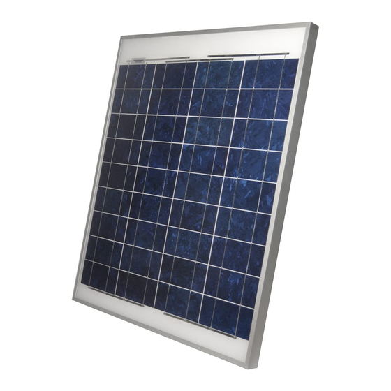
2. POWER MODULES
Kyocera "KC" series modules come in various sizes to
satisfy a full range of applications. Each module is made
of multi- crystalline cells manufactured by the "casting"
method. These cells cover nearly 100% of the module's
surface. To protect the cells from the most severe-
environmental
conditions,
between a tempered glass cover and an EVA pottant
with PVF back sheet. The entire laminate is installed in
an anodized aluminum frame for structural strength and
ease of installation.
3. APPLICATIONS
Kyocera modules are a reliable, virtually maintenance
free power supply, designed to operate efficiently in
sunlight. Kyocera solar modules are ideal for charging
storage batteries used to power remote homes,
recreational vehicles, boats, telecommunication systems
and other electric generation application.
4. MOUNTING SITE SELECTION
The solar modules should be mounted in a location
where they will receive maximum sunlight throughout the
year. In the Northern Hemisphere, the modules should
face south, and in the Southern Hemisphere, the
modules should face north. Modules facing 30 degrees
away from true South (or North) will lose approximately
10 to 15 per cent of their power output. If the module
faces 60 degrees away from true South (or North), the
power loss will be 20 to 30 per cent. When choosing a
site, avoid trees, buildings or obstructions which could
cast shadows on the solar modules especially during the
winter months when the arc of the sun is lowest over the
horizon.
they
are
encapsulated
5. MODULE TILT ANGLE
Solar modules produce the most power when they are
pointed directly at the sun. For installations where the
solar modules are mounted to a permanent structure,
the solar modules should be tilted for optimum winter
performance. As a rule, if the system power production
is adequate in the winter, it will be satisfactory during the
rest of the year. The module tilt angle is measured
between the solar modules and the ground (Figure 1).
6. MOUNTING THE MODULE
The frame of each module has fourteen 7 mm
diameter mounting holes (Figure 2). These are used to
secure the modules to the supporting structure. The
example of a ground mounted structure is shown in
Figure 3. The four holes close to the corners of the
module are most often used for mounting. Clearance
between the module frame and the mounting surface
may be required to prevent the junction box from
touching the surface, and to circulate cooling air around
the back of the module. In case the modules will be
mounted on the roof or wall of a building, the standoff
method or the rack method are recommended.
STANDOFF: The modules are supported parallel to the
surface of the building wall or roof. Clearance between
the module frames and surface of the wall or roof is
required to pre- vent wiring damage and to allow air to
circulate behind the module.
The recommended standoff height is 4.5 in.
If other mounting means are employed, this may affect
the Listing For Fire Class Ratings.
RACK: The supporting frame is used to mount modules
at correct tilt angles. The modules are not designed for
integral mounting as part of a roof or wall. The mounting
design may have an impact on the fire resistance.
1
Ú
(about 115 mm)
Advertisement
Table of Contents

Related Manuals for Kyocera KC-TYPE


Summary of Contents for Kyocera KC-TYPE
- Page 1 5. MODULE TILT ANGLE Solar modules produce the most power when they are INSTALLATION MANUAL pointed directly at the sun. For installations where the FOR KYOCERA SOLAR MODULE solar modules are mounted to a permanent structure, KC-TYPE SERIES the solar modules should be tilted for optimum winter performance.
- Page 2 7. WIRING Most of the larger KYOCERA POWER MODULES use the "G" or "M" type junction box. This box, on the back side of the module, is weatherproof and is designed to C. Using a flat blade screwdriver, remove only the be used with standard wiring or conduit connections.
- Page 3 D. Read the enclosed instructions for routing wires 9. BLOCKING DIODES through the knock-outs and clamps. (Figure 9) Blocking diodes prevent nighttime battery discharging caused and prevent modules from loss of array output and being damaged or destroyed by reverse current flow. KYOCERA modules do not contain a blocking diode when shipped from the factory, however most battery charging regulators do have this feature.
- Page 4 check the tightness of terminal screws and the general insulated and ventilated battery case specifically condition of the wiring. designed for the purpose. Also, check to be sure that mounting hardware is tight. Loose bolts could result in a damaged module or array. 12.
Need help?
Do you have a question about the KC-TYPE and is the answer not in the manual?
Questions and answers