Advertisement
Quick Links
Contents
1 About these instructions ....................................... 1
2 Description of the solar modules ......................... 1
3 Safety ...................................................................... 2
4 Assembly ................................................................ 2
5 Electrical connection ............................................. 3
6 Maintenance ........................................................... 4
7 Disclaimer ............................................................... 4
8 Customer service / Contact ................................... 4
1
About these instructions
These instructions contain information about safe handling of
KYOCERA solar modules of the KK-series.
They are directed at personnel with electro-technical qualifi-
cations and contain safety-relevant instructions for the as-
sembly, connection and maintenance of the solar modules.
IMPORTANT
The solar modules may only be mounted by personnel with
electro-technical qualifications. Appropriately qualified techni-
cians must always be deployed to service the units or remedy
faults during operation.
Please read these instructions carefully before handling the
solar module and familiarise yourself with the safety infor-
mation. After the module has been installed, hand over these
instructions to the operator of the solar modules for safekeep-
ing.
2.3
Technical data
Type designation
Electrical data (at standard test conditions: Irradiation 1000 W/m
P
[W]
max
V
[V]
oc
I
[A]
SC
V
[V]
pm
I
[A]
pm
Bypass diode (pre-installed)
Number
Temperature properties: Temperature coefficient
V
[V/°C]
oc
I
[A/°C]
sc
P
[W/°C]
max
Physical properties:
Length [mm]
Width [mm]
Height [mm]
Weight [kg]
Assembly holes
Grounding holes
Application class
Fire class
Series fuse rating [A]
KYOCERA Assembly and Maintenance Instructions, September 2017
SOLAR MODULES Assembly and Maintenance Instructions, September 2017
KK-Series: KK270P-3CD3CG, KK275P-3CD3CG, KK280P-3CD3CG
KK270P-3CD3CG
270
38.3
9.43
31.0
8.71
-1
-1.36*10
-3
5.53*10
-1.23
2
Description of the solar modules
2.1
Proper use
The solar modules use the photovoltaic principle to turn light
into electricity. The solar modules are primarily designed for
connection to an inverter to feed the energy into the public
power grid. When connecting to a charge controller, please
observe the instructions of the manufacturer of the charge
controller and accumulator. Several solar modules can be
connected in series or in parallel.
The solar modules may not be directly connected to electrical
consumers.
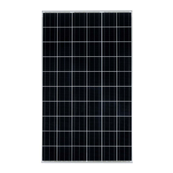
2.2
Description
The solar modules have an aluminium assembly frame with
assembly and grounding holes. The solar modules have a
junction box and solar cables with plugs for the electrical
connection. Appendix 1 of these instructions contains an
illustration of a solar module.
Designation
①
Grounding holes
②
Junction box
③
Assembly holes
④
Module frame
⑤
Solar cable
The solar modules are equipped with bypass diodes. In the
event of clouding, these minimise the losses and help to
prevent damage to the solar modules. The solar modules are
not equipped with blocking diodes preventing battery dis-
charging at night. Most PV charge regulators incorporate
nighttime disconnect feature. The solar modules comply with
the application class A in accordance with IEC 61730-1.
KK275P-3CD3CG
2
; air mass AM 1.5; module temperature 25°C)
275
38.6
9.48
31.3
8.79
3
-1
-1.37*10
-3
5.56*10
-1.25
1662
990
46
19.0
Diameter 9 mm, 4 units
Diameter 7 mm, 4 units
Class A
Class C
15
(6C-215917)
KK280P-3CD3CG
280
38.9
9.53
31.5
8.89
-1
-1.38*10
-3
5.59*10
-1.28
Advertisement

Related Manuals for Kyocera KK Series


Summary of Contents for Kyocera KK Series
-
Page 1: Table Of Contents
Width [mm] Height [mm] Weight [kg] 19.0 Assembly holes Diameter 9 mm, 4 units Grounding holes Diameter 7 mm, 4 units Application class Class A Fire class Class C Series fuse rating [A] KYOCERA Assembly and Maintenance Instructions, September 2017... -
Page 2: Safety
Do not touch the solar module with bare installed as roof mounted only. For more information about hands. the selection of the site, please contact the KYOCERA cus- NOTE tomer service. The frame of the solar module may have sharp edges and may cause injury. -
Page 3: Electrical Connection
Rustproof module clamps (at least 4 units). • Observe the minimum bending radius of 29 mm of the • Please observe the information provided by the • solar cables that are used. manufacturer when selecting the clamps. KYOCERA Assembly and Maintenance Instructions, September 2017... -
Page 4: Maintenance
Phone: 66-2-661-6400 Fax: 66-2-661-6413 secure electrical contact is created with the frame. ■ ■ ■ ■ KYOCERA (China) Sales & & & & Trading Corporation Procedure 5/F, Baolong Building, No.660-686 Jiujiang Road, Huangpu District, Please see the drawing in Appendix 1 of these in- Shanghai, P.R.China... - Page 5 Appendix 1 ④ ④ ① ① ② ⑤ ③ ③ ⑤ Grounding holes Junction box Assembly holes Module frame Solar cable ③ ③ ① ①...
- Page 6 Appendix 2 Mounting table A 2400Pa Bolting 281mm 281mm 1100mm 1100mm 100mm 100mm 100mm 100mm 100mm 100mm 100mm 100mm 100mm 100mm 100mm 100mm 100mm 100mm 100mm 100mm 281mm 281mm 1100mm 1100mm 200mm 100mm 100mm 100mm 100mm 100mm 100mm Clamping Permissible clamping range 281mm 281mm...
- Page 7 Wear suitable gloves, such as leather gloves with padding in the palm and finger areas. 2. APPLICATIONS Kyocera PV module (hereinafter referred to as “the PV FIRE RATING module”) is a reliable, virtually maintenance-free direct ・ The PV module is comprised of a glass front surface and...
- Page 8 For UL2703 certified and over (38mm) Long side clamping; attaching methods with these modules, please contact 0.14" min. min. 0.20" (5mm) Kyocera. The structure should have enough strength to (3.5mm) 1.18" and over (30mm) Short side clamping; maintain the mounting span. 0.16"...
- Page 9 1) Series: MC4 8. GROUNDING Made by Multi Contact (www.multi-contact.com) Before installation, consult the local codes and the Pole Positive Negative authorities having jurisdiction to determine the necessary grounding requirements. When installing in the US market, Model PV-KBT4/6Ⅱ-UR PV-KST4/6Ⅱ-UR attach all PV module frames to an earth ground in -...
- Page 10 : 1-800-523-2329 http://www.kyocerasolar.com/ 9. BLOCKING DIODES KYOCERA Solar do Brasil Ltda. In systems utilizing a battery, blocking diodes are typically Av. das Américas, nº 20.007, Bl 02/ Sala 105 - Recreio dos Bandeirantes Ed. Comercial Everglades Cep 22790-851 - Rio de Janeiro/ RJ – Brasil...
- Page 11 12. SPECIFICATIONS Under certain conditions, a photovoltaic module may produce more voltage and current than reported at Standard Test Conditions (STC). Refer to Section 690 of the National Electrical Code for guidance in series string sizing and choosing overcurrent protection. Module Specification Electrical Characteristics: @ STC KU255-6MCA...
- Page 12 MODULE DIMENSIONS GROUND HOLE MARKED SECTION A-A (4-0.19" [TYP.]) 0.41" 44.88" 44.69" WIRE WIRE LENGTH LENGTH INSTALLATION HOLE (4-0.35" [TYP.]) 1.18" SECTION B-B 0.47" GROUND HOLE MARKED GROUND HOLE (4-0.16" [TYP.]) 0.80" MARKED (4-0.28" [TYP.]) (0.87") 0.87" 37.24" 38.98" CLAMPING AREA 1.
Need help?
Do you have a question about the KK Series and is the answer not in the manual?
Questions and answers