Table of Contents
Advertisement
Quick Links
Contents
1 About these instructions ....................................... 1
2 Description of the solar modules ......................... 1
3 Safety ...................................................................... 2
4 Assembly ................................................................ 2
5 Electrical connection ............................................. 3
6 Maintenance ........................................................... 4
7 Disclaimer ............................................................... 4
8 Customer service / Contact ................................... 4
1
About these instructions
These instructions contain information about safe handling of
KYOCERA solar modules of the KD-series.
They are directed at personnel with electro-technical qualifi-
cations and contain safety-relevant instructions for the as-
sembly, connection and maintenance of the solar modules.
IMPORTANT
The solar modules may only be mounted by personnel with
electro-technical qualifications. Appropriately qualified techni-
cians must always be deployed to service the units or remedy
faults during operation.
Please read these instructions carefully before handling the
solar module and familiarise yourself with the safety infor-
mation. After the module has been installed, hand over these
instructions to the operator of the solar modules for safekeep-
ing.
2.3
Technical data
Type designation
Electrical data (at standard test conditions: Irradiation 1000 W/m
P
[W]
max
V
[V]
oc
I
[A]
SC
V
[V]
pm
I
[A]
pm
Bypass diode (pre-installed)
Number
Phase fuse [A]
Temperature properties: Temperature coefficient
V
[V/°C]
oc
I
[A/°C]
sc
P
[W/°C]
max
Physical properties:
Length [mm]
Width [mm]
Height [mm]
Weight [kg]
Assembly holes
Grounding holes
Application class
KYOCERA Assembly and Maintenance Instructions, August 2012
SOLAR MODULES Assembly and Maintenance Instructions I August 2012
KD240GH-4YB2
240
36.9
8.59
29.8
8.06
3
15
-1
-1.33*10
-3
5.15*10
-1.10
1662
990
46
20.0
Slotted hole 9*9.5 mm, 4 units
KD-Series: KD240GH-4YB2~KD250GH-4YB2
2
Description of the solar modules
2.1
Proper use
The solar modules use the photovoltaic principle to turn light
into electricity. The solar modules are primarily designed for
connection to an inverter to feed the energy into the public
power grid. When connecting to a charge controller, please
observe the instructions of the manufacturer of the charge
controller and accumulator. Several solar modules can be
connected in series or in parallel.
The solar modules may not be directly connected to electrical
consumers.
2.2
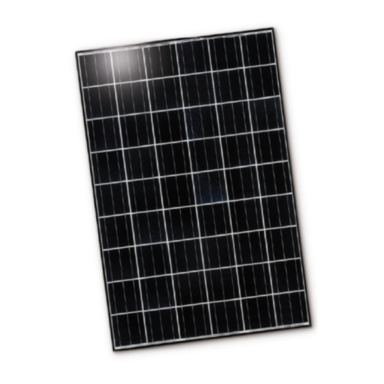
Description
The solar modules have an aluminium assembly frame with
assembly and grounding holes. The solar modules have a
junction box and solar cables with plugs for the electrical
connection. Appendix 1 of these instructions contains an
illustration of a solar module.
①
②
③
④
⑤
The solar modules are equipped with bypass diodes. In the
event of clouding, these minimise the losses and help to
prevent damage to the solar modules. The solar modules are
not equipped with blocking diodes preventing battery dis-
charging at night. Most PV charge regulators incorporate
nighttime disconnect feature. The solar modules comply with
the application class A in accordance with IEC/EN 61730-1.
KD245GH-4YB2
2
; air mass AM 1.5; module temperature 25°C)
245
36.9
8.91
29.8
8.23
3
15
-1
-1.33*10
-3
5.35*10
-1.12
1662
990
46
20.0
Diameter 7 mm, 4 units
Class A
Designation
Grounding holes
Junction box
Assembly holes
Module frame
Solar cable
KD250GH-4YB2
250
36.9
9.09
29.8
8.39
3
15
-1
-1.33*10
-3
5.45*10
-1.15
1662
990
46
20.0
ENG
Advertisement
Table of Contents

Subscribe to Our Youtube Channel
Related Manuals for Kyocera KD240GH-4YB2


Summary of Contents for Kyocera KD240GH-4YB2
-
Page 1: Table Of Contents
Length [mm] 1662 1662 1662 Width [mm] Height [mm] Weight [kg] 20.0 20.0 20.0 Assembly holes Slotted hole 9*9.5 mm, 4 units Grounding holes Diameter 7 mm, 4 units Application class Class A KYOCERA Assembly and Maintenance Instructions, August 2012... -
Page 2: Safety
NOTE a fire-resistant surface. The frame of the solar module may have sharp edges and may cause injury. Wear suitable gloves, such as leather gloves with padding in the palm and finger areas. KYOCERA Assembly and Maintenance Instructions, August 2012... -
Page 3: Electrical Connection
R51-7/P51-7 (or MC4: PV-KST4/KBT4) for further series or - must not touch the front glass. - must not cast a shadow on the front glass. parallel wiring. - must not damage the surface of the frame. KYOCERA Assembly and Maintenance Instructions, August 2012... -
Page 4: Maintenance
Observe the minimum bending radius of 24.5 mm of is not strictly observed. KYOCERA will not assume any liabil- the solar cables that are used. ity for damage arising from improper use, wrong assembly, operation or maintenance. - Page 5 Mounting table A-1 Befestigung an der langen Rahmenseite Montagetabelle A-1 Fijación al lado largo del bastidor Tabla de montaje A-1 KD240GH-4YB2 Fixation sur la partie longue du cadre Tableau de montage A-1 Fissaggio sul lato lungo del telaio Tabella di montaggio A-1 KD245GH-4YB2 Upevnění...
- Page 6 Mounting table A-2 Befestigung an der kurzen Rahmenseite Montagetabelle A-2 Fijación al lado corto del bastidor Tabla de montaje A-2 KD240GH-4YB2 Fixation sur la partie courte du cadre Tableau de montage A-2 Fissaggio sul lato corto del telaio Tabella di montaggio A-2 KD245GH-4YB2 Upevnění...
Need help?
Do you have a question about the KD240GH-4YB2 and is the answer not in the manual?
Questions and answers