Kyocera KD Series Assembly And Maintenance Instructions
Solar modules
Hide thumbs
Also See for KD Series:
- Mounting manual (4 pages) ,
- Assembly and maintenance instructions (6 pages)
Advertisement
Quick Links
SOLAR MODULES Assembly and Maintenance Instructions I March 2010
Contents
1 About these instructions ............................................. 1
2 Description of the solar modules ................................ 1
3 Safety .......................................................................... 2
4 Assembly ..................................................................... 2
5 Electrical connection ................................................... 3
6 Maintenance ............................................................... 4
7 Disclaimer ................................................................... 4
8 Customer service / Contact ......................................... 4
1
About these instructions
These instructions contain information about safe handling of
KYOCERA solar modules of the KD-series.
They are directed at personnel with electro-technical qualifi-
cations and contain safety-relevant instructions for the as-
sembly, connection and maintenance of the solar modules.
IMPORTANT
The solar modules may only be mounted by personnel with
electro-technical qualifications. Appropriately qualified tech-
nicians must always be deployed to service the units or rem-
edy faults during operation.
Please read these instructions carefully before handling the
solar module and familiarise yourself with the safety informa-
tion. After the module has been installed, hand over these
instructions to the operator of the solar modules for safe-
keeping.
2.3
Technical data
KD135GH
KD185GH
KD210GH
Type designation
-2PU
-2PU
-2PU
Electrical data (at standard test conditions: Irradiation 1000 W/m
P
[W]
135
185
210
max
V
[V]
22.1
29.5
33.2
oc
I
[A]
8.37
8.58
8.58
SC
V
[V]
17.7
23.6
26.6
pm
I
[A]
7.63
7.84
7.90
pm
Bypass diode (pre-installed)
Number
2
3
3
Phase fuse [A]
15
15
15
Temperature properties: Temperature coefficient
-1
-1
-1
V
[V/°C]
-0.80*10
-1.06*10
-1.20*10
oc
-3
-3
-3
I
[A/°C]
5.02*10
5.15*10
5.15*10
sc
-1
-1
-1
P
[W/°C]
-6.14*10
-8.40*10
-9.60*10
max
Physical properties:
Length [mm]
1500
1338
1500
Width [mm]
668
990
990
Height [mm]
46
46
46
Weight [kg]
12.5
16.0
18.0
Assembly holes
Grounding holes
Application class
KYOCERA Assembly and Maintenance Instructions, March 2010
KD-Series: KD135GH-2PU-KD235GH-2PB
2
Description of the solar modules
2.1
Proper use
The solar modules use the photovoltaic principle to turn light
into electricity. The solar modules are primarily designed for
connection to an inverter to feed the energy into the public
power grid. When connecting to a charge controller, please
observe the instructions of the manufacturer of the charge
controller and accumulator. Several solar modules can be
connected in series or in parallel.
The solar modules may not be directly connected to electrical
consumers.
2.2
Description
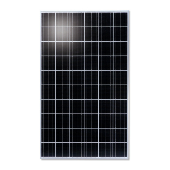
The solar modules have an aluminium assembly frame with
assembly and grounding holes. The solar modules have a
junction box and solar cables with plugs for the electrical
connection. Appendix 1 of these instructions contains an
illustration of a solar module.
Designation
①
Grounding holes
②
Junction box
③
Assembly holes
④
Module frame
⑤
Solar cable
The solar modules are equipped with bypass diodes. In the
event of clouding, these minimise the losses and help to
prevent damage to the solar modules. The solar modules are
not equipped with blocking diodes preventing battery dis-
charging at night. Most PV charge regulators incorporate
nighttime disconnect feature. The solar modules comply with
the application class A in accordance with IEC/EN 61730-1.
KD215GH
KD230GH
KD230GH
KD235GH
KD235GH
-2PU
-2FB
-2PB
-2FB
2
; air mass AM 1.5; module temperature 25°C)
215
230
230
235
33.2
36.9
36.9
36.9
8.78
8.36
8.36
8.55
26.6
29.8
29.8
29.8
8.09
7.72
7.72
7.89
3
3
3
3
15
15
15
15
-1
-1
-1
-1
-1.20*10
-1.33*10
-1.33*10
-1.33*10
-1.33*10
-3
-3
-3
-3
5.27*10
5.02*10
5.02*10
5.13*10
5.13*10
-1
-9.91*10
-1.04
-1.04
-1.07
1500
1662
1662
1662
990
990
990
990
46
46
46
46
18.0
21.0
21.0
21.0
Diameter 9 mm, 4 units
Diameter 9 mm, 4 units
Class A
ENG
3
Solar modules generate power, producing voltage and cur-
rent as soon as they are exposed to light. A single solar mod-
ule generates a voltage of below 50 VDC; if several modules
are connected in series, the voltages of the individual mod-
ules accumulate and can pose a hazard.
-2PB
235
36.9
8.55
29.8
7.89
3
15
-1
-3
-1.07
1662
990
46
21.0
KYOCERA Assembly and Maintenance Instructions, March 2010
Safety
Hazard!
Potentially fatal risk due to electrical shock if
damaged solar modules are touched.
•
Only touch solar modules with fractured or
broken front glass or a damaged rear foil if
you are wearing rubber gloves.
•
Only touch damaged solar modules if it is
absolutely necessary.
Warning!
Risk of falling when working on roofs.
•
Use suitable fall protection equipment.
•
Observe the accident prevention regulations.
Warning!
Risk of injury from falling objects.
•
Cordon off a safe distance around the haz-
ardous zone when working on roofs.
Caution!
To avoid damage to the solar module, please
observe the following points:
•
Do not apply paint or any adhesives to the
rear side of the solar module.
•
Never use the junction box or the solar cable
to carry the unit.
•
Do not expose the solar module to concen-
trated light.
•
Do not allow any objects to fall upon the
solar module.
•
Avoid scratches to the front glass.
Caution!
Risk of breaking the solar module.
•
Do not walk across or step on the solar
module.
4
Assembly
Assembly work may only be performed by
trained and qualified personnel.
4.1
Safety information relating to assembly
Caution!
KYOCERA solar modules are "non-explosion-
protected operating equipment".
•
Do not install the solar module close to
flammable gases or vapours.
Hazard!
Potentially fatal risk if live parts are touched.
•
Cover the solar module with opaque foils or
materials during assembly.
Warning!
Risk of falling when working on roofs.
•
Use suitable fall protection equipment.
•
Do not perform assembly work in strong
winds.
•
Only perform assembly work in dry weather
conditions.
•
Observe the accident prevention regulations.
4.2
Select the location
NOTE
Before installing the PV system, contact local authorities to
determine the necessary permits, installation and inspection
requirements. During assembly, pay attention to the local
building standards.
The solar modules can be installed on roofs or open space on
support structures. To achieve maximum power yields for
feeding into the public grid, the following should be observed
when selecting the installation site: The solar irradiation
should be as high as possible distributed throughout the year.
To this end, the surface of the solar modules in the northern
hemisphere must face south. In Europe, the ideal module
slope is approx. 30° - 40°. While a bigger module slope leads
to energy losses, smaller module slope can also lead to high
accumulations of non-slipping snow on the module, which
might cause damages to the module or its frame. The solar
modules should not be exposed to shadows cast by trees or
buildings as this would lead to energy losses. For more infor-
mation about the selection of the site, please contact the
KYOCERA customer service.
4.3
Preparatory work for assembly
The solar module must be mounted to a support structure.
Please observe the information provided by the mount manu-
facturer when selecting the support structure.
If installed on a roof, the solar modules must be mounted on
a fire-resistant surface.
Advertisement


Need help?
Do you have a question about the KD Series and is the answer not in the manual?
Questions and answers