
Related Manuals for Circutor line-TCPRS1


Summarization of Contents
Safety Precautions
DANGER
Warns of risks resulting in personal injury or material damage.
ATTENTION
Indicates special attention is required for a specific point.
Disclaimer
CIRCUTOR, SA reserves the right to modify features or product manual without prior notice.
Verification Upon Reception
Product Description
Overview of expansion modules for line-CVM and line-EDS devices.
Installation of the Device
Preliminary Recommendations
Safety measures and personnel qualifications for device installation.
Installation
Steps for installing the expansion module on a DIN rail.
Panel Adapter 72 x 72 mm
Details on using a panel adapter for 72x72mm panels.
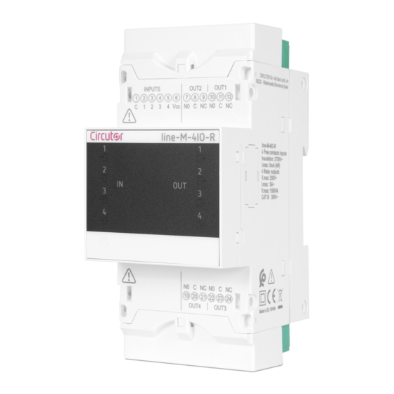
LINE-M-4IO-R
Device Terminals
Identification and description of device terminals for LINE-M-4IO-R.
Connection Diagram
Wiring diagrams for enabling digital inputs and connecting outputs.
LED Indicators
Explanation of the LED indicators for the LINE-M-4IO-R module.
Configuration LINE-M-4IO-R
Guide to configuring the LINE-M-4IO-R via the line-CVM display.
Configuration of Digital Inputs 1 ... 4
Configuration of digital inputs for LINE-M-4IO-R, including mode and name.
Mode and Name of Digital Input x
Details on configuring input mode (IMPULSE, STATUS, TARIFF) and name.
Units and Energy per Pulse
Setting units and energy per pulse for pulse input mode.
Decimals
Configuring the number of decimal places for inputs.
Input Signal Logic
Setting input signal logic (POSITIVE or NEGATIVE).
Configuration of Relay Outputs 1 ... 4
Configuration of relay outputs for LINE-M-4IO-R.
Variable
Selecting the variable for relay output programming.
Maximum and Minimum Values
Setting maximum and minimum values for alarm configuration.
Connection and Disconnection Delay
Configuring delays for alarm connection and disconnection.
Hysteresis and Status of Contacts
Setting hysteresis value and contact status.
Latch
Configuring alarm latch and latching time.
Energy per Pulse and Contact Status
Configuring energy per pulse and contact status for energy outputs.
Pulse
Configuring pulse width for pulse outputs.
Manual Operation of the Relay Output
Manual control of relay output status and contact type.
Modbus Memory Map LINE-M-4IO-R
Modbus memory map for LINE-M-4IO-R inputs, outputs, alarms, and variables.
Input and Output Status
Modbus addresses for input and output status.
Pulse Meters
Modbus addresses for pulse meter counters.
Alarms
Modbus addresses for alarm activation dates.
Device Configuration Variables
Modbus addresses for device configuration variables.
Digital Input Configuration
Modbus addresses for digital input configuration.
Relay Output Configuration
Modbus addresses for relay output configuration.
Technical Features: LINE-M-4IO-R
Technical specifications for the LINE-M-4IO-R module.
LINE-M-4IO-T
Device Terminals
Identification and description of device terminals for LINE-M-4IO-T.
Connection Diagram
Wiring diagrams for LINE-M-4IO-T digital inputs and transistor outputs.
LED Indicators
Explanation of the LED indicators for the LINE-M-4IO-T module.
Configuration LINE-M-4IO-T
Guide to configuring the LINE-M-4IO-T via the line-CVM display.
Configuration of Digital Inputs 1 ... 4
Configuration of digital inputs for LINE-M-4IO-T.
Configuration of Transistor Outputs 1 ... 4
Configuration of transistor outputs for LINE-M-4IO-T.
Modbus Memory Map LINE-M-4IO-T
Modbus memory map for LINE-M-4IO-T.
Technical Features: LINE-M-4IO-T
Technical specifications for the LINE-M-4IO-T module.
LINE-M-4IO-A
Device Terminals
Identification and description of device terminals for LINE-M-4IO-A.
Connection Diagram
Wiring diagram for LINE-M-4IO-A analogue inputs and outputs.
LED Indicators
Explanation of the LED indicators for the LINE-M-4IO-A module.
Configuration LINE-M-410-A
Guide to configuring the LINE-M-4IO-A via the line-CVM display.
Configuration of Analogue Inputs 1 ... 4
Configuration of analogue inputs for LINE-M-4IO-A.
Analogue Input x Name and Scale
Setting the name and scale for analogue inputs.
Zero and Full Scale
Configuring zero and full scale values for analogue inputs.
Units and Decimal No.
Setting units and number of decimals for analogue inputs.
Configuration of Analogue Outputs 1 ... 4
Configuration of analogue outputs for LINE-M-4IO-A.
Variable and Scale
Setting variable and scale for analogue outputs.
Zero and Full Scale
Configuring zero and full scale values for analogue outputs.
Modbus Memory Map LINE-M-4IO-A
Modbus memory map for LINE-M-4IO-A.
Analogue Input
Modbus addresses for analogue input values.
Device Configuration Variables
Modbus addresses for device configuration variables.
Analogue Input Configuration
Modbus addresses for analogue input configuration.
Analogue Output Configuration
Modbus addresses for analogue output configuration.
Technical Features: LINE-M-4IO-A
Technical specifications for the LINE-M-4IO-A module.
LINE-M-410-RV
Device Terminals
Identification and description of device terminals for LINE-M-4IO-RV.
Connection Diagram
Wiring diagram for LINE-M-4IO-RV digital inputs and relay outputs.
LED Indicators
Explanation of the LED indicators for the LINE-M-410-RV module.
Configuration LINE-M-410-RV
Guide to configuring the LINE-M-410-RV via the line-CVM display.
Configuration of Digital Inputs 1 ... 4
Configuration of digital inputs for LINE-M-410-RV.
Configuration of Relay Outputs 1 ... 4
Configuration of relay outputs for LINE-M-410-RV.
Modbus Memory Map Line-M-410-RV
Modbus memory map for LINE-M-410-RV.
Technical Features: Line-M-410-RV
Technical specifications for the LINE-M-410-RV module.
Line-M-EXT-PS
Installation
Installation instructions for the LINE-M-EXT-PS power adapter.
Device Terminals
Identification of device terminals for LINE-M-EXT-PS.
Connection Diagram
Connection diagrams for LINE-M-EXT-PS.
Maximum Connection
Diagram showing maximum connection configurations.
Multiple Connection Line-M-EXT-PS
Diagrams for multiple LINE-M-EXT-PS connections.
LED Indicators
Explanation of the LED indicator for the LINE-M-EXT-PS module.
Technical Features: Line-M-EXT-PS
Technical specifications for the LINE-M-EXT-PS module.
line-M-3G
Installation of the SIM Card
Instructions for installing the SIM card in the LINE-M-3G module.
LED Indicators
Explanation of the LED indicators for the LINE-M-3G module.
Communications
Information on wireless communication protocols and usage.
Usage Environment and Health
Precautions regarding wireless communications usage and health.
3G Communications
Information about 3G connectivity setup for LINE-M-3G.
Technical Features: line-M-3G
Technical specifications for the LINE-M-3G module.
line-TCPRS1
Installation
Installation requirements for the LINE-TCPRS1 gateway.
Device Terminals
Identification of device terminals for LINE-TCPRS1.
LED Indicators
Explanation of LED indicators for the LINE-TCPRS1 gateway.
Communications
Information on device communication methods and settings.
Usage Environment and Health
Precautions regarding wireless communications usage and health.
Wi-Fi Communications
Information on Wi-Fi communication standards for LINE-TCPRS1.
Bluetooth® Communications
Information on Bluetooth communication for LINE-TCPRS1.
Configuration Website
Accessing and using the LINE-TCPRS1 configuration website.
Mobile App
Information on the MyConfig mobile app for LINE-TCPRS1.
Technical Features: line-TCPRS1
Technical specifications for the LINE-TCPRS1 gateway.
line-M-20I
Installation
Installation constraints for the LINE-M-20I centraliser.
Device Terminals
Identification of device terminals for LINE-M-20I.
Connection Diagram
Connection diagram for the LINE-M-20I centraliser.
LED Indicators
Explanation of LED indicators for the LINE-M-20I centraliser.
Modbus Memory Map
Modbus memory map for LINE-M-20I.
Digital Inputs
Modbus map for digital input status of LINE-M-20I.
Pulse Meters
Modbus map for pulse meters of LINE-M-20I.
Other Device Parameters
Modbus map for other device parameters of LINE-M-20I.
Device Configuration Variables
Modbus map for device configuration variables of LINE-M-20I.
Digital Input Configuration
Modbus map for digital input configuration of LINE-M-20I.
Technical Features: line-M-20I
Technical specifications for the LINE-M-20I centraliser.
line-LM20I-TCP kit
Installation
Installation requirements for the LINE-LM20I-TCP kit.
Device Terminals
Identification of device terminals for LINE-LM20I-TCP kit.
Connection Diagram
Connection diagram for the LINE-LM20I-TCP kit.
LED Indicators
Explanation of LED indicators for the LINE-LM20I-TCP kit.
Modbus Memory Map
Modbus memory map for LINE-LM20I-TCP kit.
Communications
Information on device communication methods and settings.
Usage Environment and Health
Precautions regarding wireless communications usage and health.
Wi-Fi Communications
Information on Wi-Fi communication standards for LINE-LM20I-TCP kit.
Bluetooth® Communications
Information on Bluetooth communication for LINE-LM20I-TCP kit.
Technical Features: line-LM20I-TCP kit
Technical specifications for the LINE-LM20I-TCP kit.
line-LM40I-TCP kit
Installation
Installation requirements for the LINE-LM40I-TCP kit.
Device Terminals
Identification of device terminals for LINE-LM40I-TCP kit.
Connection Diagram
Connection diagram for the LINE-LM40I-TCP kit.
LED Indicators
Explanation of LED indicators for the LINE-LM40I-TCP kit.
Modbus Memory Map
Modbus memory map for LINE-LM40I-TCP kit.
Communications
Information on device communication methods and settings.
Usage Environment and Health
Precautions regarding wireless communications usage and health.
Wi-Fi Communications
Information on Wi-Fi communication standards for LINE-LM40I-TCP kit.
Bluetooth® Communications
Information on Bluetooth communication for LINE-LM40I-TCP kit.
Technical Features: line-LM40I-TCP kit
Technical specifications for the LINE-LM40I-TCP kit.
Maintenance and Technical Service
Guarantee
Details on CIRCUTOR product guarantee terms and conditions.
Annex A. Configuration Menus
A.1.- LINE-M-4IO-R, LINE-M-4IO-T and LINE-M-4IO-RV
Configuration menu flowcharts for specific modules.
A.2.- LINE-M-4IO-A
Configuration menu flowcharts for the LINE-M-4IO-A module.
Need help?
Do you have a question about the line-TCPRS1 and is the answer not in the manual?
Questions and answers