Advertisement
Quick Links
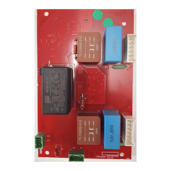
CPC-2M
PLACA DE CONTROL PARA BATERÍAS
DE CONDENSADORES ESTÁTICAS
CONTROL BOARD FOR STATIC CAPACITOR BANKS
ES
EN
ES
Este manual es una guía de instalación del CPC-2M. Para más infor-
mación, se puede descargar el manual completo en la página web de
CIRCUTOR: www.circutor.com
¡IMPORTANTE!
Antes de efectuar cualquier operación de instalación, re-
paración o manipulación de cualquiera de las conexiones
del equipo debe desconectar el aparato de toda fuente de
alimentación, tanto alimentación como de medida. Cuando
sospeche un mal funcionamiento del equipo póngase en
contacto con el servicio posventa. El diseño del equipo
permite una sustitución rápida en caso de avería.
El fabricante del equipo no se hace responsable de
daños cualesquiera que sean en caso de que el usuario
o instalador no haga caso de las advertencias y/o reco-
mendaciones indicadas en este manual ni por los daños
derivados de la utilización de productos o accesorios no
originales o de otras marcas.
1. DESCRIPCIÓN
La placa CPC-2M es un controlador para interruptores estáticos trifásicos
(2 bloques de tiristor-diodo). La placa gestiona las ordenes de conexión y
desconexión dadas por algún regulador externo y se encarga de la sincro-
nización de cada fase con su respectiva tensión de alimentación, de forma
que el interruptor conecte a paso por cero de la tensión, y desconecte a
paso por cero de la corriente.
La placa CPC-2M se aplica para la compensación rápida y sin transitorios
del factor de potencia (FP) basándose en la inserción a la red de conden-
sadores o de grupos LC de compensación y filtrado de armónicos.
Las prestaciones básicas de la placa CPC-2M son las siguientes:
Sistema de detección de paso por cero, preparado para conexión segura
en caso de las sobretensiones típicas de los filtros de 7% y 14%.
Mando por contacto exterior para señal de 12 V
.
Compatible con los reguladores de alta gama tipo COMPUTER SMART
II FAST-12VDC+.
Aislamientos reforzados para aplicaciones hasta 440V fase-fase, sin
neutro.
Cebado de módulos tiristor-diodo a través de transformadores de im-
pulsos de alto grado de aislamiento.
Control mediante microprocesador, con algoritmo inteligente.
2. INSTALACIÓN
La placa CPC-2M debe instalarse siempre dentro de un armario con llave,
con la imposibilidad de contacto directo.
¡IMPORTANTE!
Tener en cuenta que con el equipo conectado, los bornes
pueden ser peligrosos al tacto, y la apertura de cubiertas
ó eliminación de elementos puede dar acceso a partes
peligrosas al tacto. El equipo no debe ser utilizado
hasta que haya finalizado por completo su instalación
Guía de Instalación del módulo de control estático EMB-M-2PH-80-400:
Manual de sustitución del módulo de control estático EM-2-80-400-FRE
por un módulo EN-2M-80-400-FRE:
EN
This manual is a CPC-2M installation guide. For further information,
please download the full manual from the CIRCUTOR web site:
www.circutor.com
IMPORTANT!
The device must be disconnected from its power supply
sources (power supply and measurement) before under-
taking any installation, repair or handling operations on
the device's connections. Contact the after-sales service
if you suspect that there is an operational fault in the de-
vice The device has been designed for easy replacement
in case of malfunction.
The manufacturer of the device is not responsible for
any damage resulting from failure by the user or in-
staller to heed the warnings and/or recommendations
set out in this manual, nor for damage resulting from
the use of non-original products or accessories or those
made by other manufacturers.
1. DESCRIPTION
The CPC-2M board is a controller for three-phase static switches (2 thy-
ristor-diode blocks). The board panel manages the connect and disconnect
commands given by an external regulator, and it synchronizes each phase
with its respective power supply voltage, such that the switch connects at
zero voltage and it disconnects at zero current.
The CPC-2M board is used for fast and transient-free compensation of
the power factor (PF), which it does by inserting capacitors or LC banks
into the network to compensate and filter harmonics.
The basic features of the CPC-2M board are as follows:
Zero crossing detection system, designed to connect safely in the event
of overvoltages typical of 7% and 14% filters.
Control through external contact of 12V
signal.
Compatible with high-end COMPUTER SMART II FAST-12VDC+ regula-
tors.
Reinforced insulation for applications of up to 440V phase-phase, with
no neutral.
Priming of thyristor-diode modules through high-insulation impulse
transformers.
Microprocessor control, with an intelligent algorithm.
2. INSTALLATION
The CPC-2M board must always be installed inside a locked cabinet, with
the impossibility of direct contact.
IMPORTANT!
Take into account that when the device is connected, the
terminals may be hazardous to the touch, and opening
the covers or removing elements may provide access to
parts that are dangerous to the touch. Do not use the
device until it is fully installed
Installation guide of the static control module EMB-M-2PH-80-400:
Manual for replacing the EM-2-80-400-FRE static control module with
an EN-2M-80-400-FRE module:
LED CPU/POWER
LED COMPUTER
COM
ACT
A2
A1
○
●
. ◒
LED Apagado / LED OFF.
LED Encendido / LED ON
LED Parpadeando / LED blinking.
LEDs
Estado /State
Descripción / Description
Sin señal de activación desde el regulador de reactiva / No activation signal
○
from the power factor regulator.
Placa alimentada. Detección de tensión trifásica incorrecta, la placa no
◒
CPU/POWER
activará los tiristores. / Powered board. Detection of incorrect three-phase
voltage, the board will not activate the thyristors.
Placa alimentada. Detección de tensión trifásica correcta. / Powered board.
●
Detection of correct three-phase voltage.
Señal de activación desde el regulador de reactiva. / Activation signal from
●
COMPUTER
the power factor regulator.
●
Tiristor-Diodo de la fase 1 conectado. / Phase-1 thyristor-diode connected.
FASE TH1
Tiristor-Diodo de la fase 1 no conectado. / Phase-1 thyristor-diode not
PHASE TH1
◒
connected.
●
Tiristor-Diodo de la fase 2 conectado. / Phase-2 thyristor-diode connected.
FASE TH2
Tiristor-Diodo de la fase 2 no conectado. / Phase-2 thyristor-diode not
PHASE TH2
◒
connected.
Nota: Las imágenes de los equipos son de uso ilustrativo únicamente y pueden diferir del equipo original.
Note: Device images are for illustrative purposes only and may differ from the actual device.
LED FASE TH2
LED PHASE TH2
K2
K2
G2
AN2
LED FASE TH1
LED PHASE TH1
K1
K1
G1
AN1
Advertisement

Related Manuals for Circutor CPC-2M


Summary of Contents for Circutor CPC-2M
- Page 1 LED FASE TH2 LED PHASE TH2 Este manual es una guía de instalación del CPC-2M. Para más infor- This manual is a CPC-2M installation guide. For further information, mación, se puede descargar el manual completo en la página web de please download the full manual from the CIRCUTOR web site: CIRCUTOR: www.circutor.com...
- Page 2 COM (+), Señal externa de activación / External activation signal ACT (-), Señal externa de activación / External activation signal Servicio técnico / Technical service CIRCUTOR SAT: 902 449 459 (SPAIN) / (+34) 937 452 919 (out of Spain) Vial Sant Jordi, s/n...
Need help?
Do you have a question about the CPC-2M and is the answer not in the manual?
Questions and answers