Sign In
Upload
Download
Table of Contents
Contents
Add to my manuals
Delete from my manuals
Share
URL of this page:
HTML Link:
Bookmark this page
Add
Manual will be automatically added to "My Manuals"
Print this page
×
Bookmark added
×
Added to my manuals
Manuals
Brands
Circutor Manuals
Control Unit
line-M-4IO-R
Instruction manual
Circutor line-M-4IO-R Instruction Manual
Expansion modules
Hide thumbs
1
2
3
Table Of Contents
4
5
6
7
8
9
10
11
12
13
14
15
16
17
18
19
20
21
22
23
24
25
26
27
28
29
30
31
32
33
34
35
36
37
38
39
40
41
42
43
44
45
46
47
48
49
50
51
52
53
54
55
56
57
58
59
60
61
62
63
64
65
66
67
68
69
70
71
72
73
74
75
76
77
78
79
80
81
82
83
84
85
86
87
88
89
90
91
92
93
94
95
96
97
98
99
100
101
102
103
104
105
106
107
108
109
110
111
112
page
of
112
Go
/
112
Contents
Table of Contents
Bookmarks
Table of Contents
Safety Precautions
Disclaimer
Contents
Table of Contents
Revision Log
1 Symbols
2 Verification Upon Reception
3 Product Description
3�- Installation of the Device
3�1�- Preliminary Recommendations
3�2�- Installation
3 �3�- PANEL ADAPTER 72 X 72 MM
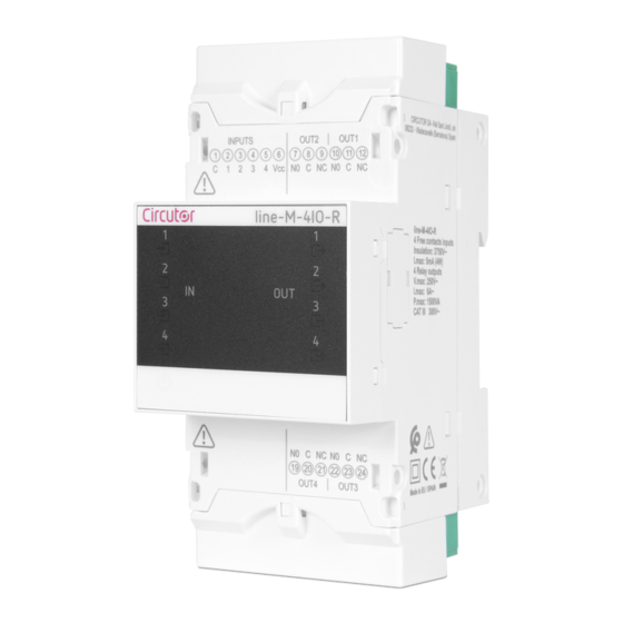
4�- Line-M-4Io-R
4�1�- Device Terminals
4�2� - Connection Diagram
4�3 �- Led Indicators
4�4�- CONFIGURATION Line-M-4IO-R
4�4�1�- Configuration of Digital Inputs 1
4�4�2�- Configuration of Relay Outputs 1
4�5�- MODBUS MEMORY MAP Line-M-4IO
4�5�1�- Input and Output Status
4�5�2�- Pulse Meters
4�5�3�- Alarms
4�5�4�- Device Configuration Variables
4 �6�- TECHNICAL FEATURES: Line-M-4IO
Line-M-4Io
5�1�- Device Terminals
5�2� - Connection Diagram
5�3 �- Led Indicators
5�4�- CONFIGURATION Line-M-4IO-T
5�4�1�- Configuration of Digital Inputs 1
5�4�2�- Configuration of Transistor Outputs 1
5�5�- MODBUS MEMORY MAP Line-M-4IO
5�5�1�- Input and Output Status
5�5�2�- Pulse Meters
5�5�3�- Alarms
5�5�4�- Device Configuration Variables
5�6�- TECHNICAL FEATURES: Line-M-4IO
6 Line-M-4Io
6�1�- Device Terminals
6�2� - Connection Diagram
6�3 �- Led Indicators
6�4�- CONFIGURATION Line-M-410-A
6�4�1�- Configuration of Analogue Inputs 1
6�4�2�- Configuration of Analogue Outputs 1
6�5�- MODBUS MEMORY MAP Line-M-4IO-A
6�5�1�- Analogue Input
6�5�2�- Device Configuration Variables
6�6�- TECHNICAL FEATURES: Line-M-4IO
7 �- Line-M-4Io
7�1�- Device Terminals
7�2� - Connection Diagram
7�3 �- Led Indicators
7�4�- CONFIGURATION Line-M-4IO-RV
7�4�1�- Configuration of Digital Inputs 1
7�4�2�- Configuration of Relay Outputs 1
7�5�- MODBUS MEMORY MAP Line-M-410-RV
7�5�1�- Input and Output Status
7�5�2�- Alarms
7�5�3�- Device Configuration Variables
7�6�- TECHNICAL FEATURES: Line
8 �- Line-M-Ext
8�1�- Installation
8�2�- Device Terminals
8�3� - Connection Diagram
8�3�1�- Maximum Connection
8�3�2�- MULTIPLE CONNECTION Line-M-EXT-PS
8�4� - Led Indicators
8�5� - TECHNICAL FEATURES: Line-M-EXT
9 �- Line-M-3G
9�1�- Installation of the Sim Card
9�2�- Led Indicators
9�3�- Communications
9�3�1�- Usage Environment and Health
9�3�2�- 3G Communications
9�4�- TECHNICAL FEATURES: Line-M-3G
10 �- Line-Tcprs1
10�1�- Installation
10�2�- Device Terminals
10�3�- Led Indicators
10�4�- Communications
10�4�1�- Usage Environment and Health
10�4�2�- Wi-Fi COMMUNICATIONS
10�4�3�- Bluetooth® COMMUNICATIONS
10�4�4�- Configuration Website
10�4�5�- Mobile App
10�5�- TECHNICAL FEATURES: Line-TCPRS1
11 �- Line-M-20I
11�1�- Installation
11�2�- Device Terminals
11�3�- Connection Diagram
11�4�- Led Indicators
11�5�- Modbus Memory Map
11�5�1�- Digital Inputs
11�5�2�- Pulse Meters
11�5�3�- Other Device Parameters
11�5�4�- Device Configuration Variables
11�6�- TECHNICAL FEATURES: Line-M-20I
12 �- Line-Lm20I-Tcp Kit
12�1�- Installation
12�2�- Device Terminals
12�3�- Connection Diagram
12�4�- Led Indicators
12�5�- Modbus Memory Map
12�6�- Communications
12�6�1�- Usage Environment and Health
12�6�2�- Wi-Fi COMMUNICATIONS
12�6�3�- Bluetooth® COMMUNICATIONS
12�6�4�- Configuration Website
12�6�5�- Mobile App
12�7�- TECHNICAL FEATURES: Line-LM20I-TCP Kit
13 �- Line-Lm40I-Tcp Kit
13�1�- Installation
13�2�- Device Terminals
13�3�- Connection Diagram
13�4�- Led Indicators
13�5�- Modbus Memory Map
13�6�- Communications
13�6�1�- Usage Environment and Health
13�6�2�- Wi-Fi COMMUNICATIONS
13�6�3�- Bluetooth® COMMUNICATIONS
13�6�4�- Configuration Website
13�6�5�- Mobile App
13�7�- TECHNICAL FEATURES: Line-LM40I-TCP Kit
14 �- Maintenance and Technical Service
15 .- Guarantee
16 �- Ce Certificate
Annex A.- Configuration Menus
A�1�- Line-M-4IO-R, Line-M-4IO-T and Line-M-4IO
A�2�- Line-M-4IO
Advertisement
Quick Links
1
3�- Installation of the Device
Download this manual
Expansion modules for the line-CVM and
line-EDS devices
INSTRUCTION MANUAL
(M239B01-03-20B)
Table of
Contents
Previous
Page
Next
Page
1
2
3
4
5
Advertisement
Table of Contents
Need help?
Do you have a question about the line-M-4IO-R and is the answer not in the manual?
Ask a question
Questions and answers
Related Manuals for Circutor line-M-4IO-R
Control Unit Circutor line-EDS-PS Instruction Manual
Energy manager (30 pages)
Control Unit Circutor line-EDS-PS Instruction Manual
Energy manager (30 pages)
Control Unit Circutor line-TCPRS1 Instruction Manual
Expansion modules (112 pages)
Control Unit Circutor CBS-4 Series Instruction Manual
Control device for electronic earth leakage protection relays (29 pages)
Control Unit Circutor CDP-0 Instruction Manual
Dynamic power control (80 pages)
Control Unit Circutor CPC-2M Manual
Control board for static capacitor banks (2 pages)
Control Unit Circutor EDS Configuration Manual
Xml services, energy managers (16 pages)
Control Unit CIRCUTOR EDS User's And Operator's Manual
Energy efficiency manager (5 pages)
Control Unit Circutor EDS-3G Quick Start Manual
Energy efficiency manager (7 pages)
This manual is also suitable for:
Line-m-4io-t
Line-m-4io-a
Line-m-4io-rv
Line-m-ext-ps
Line-m-3g
Line-m-20i
...
Show all
Line-tcprs1
Line-lm20i-tcp kit
Line-lm40i-tcp kit
Table of Contents
Print
Rename the bookmark
Delete bookmark?
Delete from my manuals?
Login
Sign In
OR
Sign in with Facebook
Sign in with Google
Upload manual
Upload from disk
Upload from URL


Need help?
Do you have a question about the line-M-4IO-R and is the answer not in the manual?
Questions and answers