Table of Contents
Advertisement
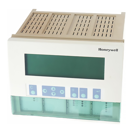
HONEYWELL EXCEL 5000 OPEN SYSTEM
Revision Overview ....................................................................................................................................................................... 3
Safety Instructions ....................................................................................................................................................................... 4
MOUNTING .................................................................................................................................................................................... 5
Electrical Connections ............................................................................................................................................................... 16
® U.S. Registered Trademark
Copyright © 2013 Honeywell Inc. • All Rights Reserved
Control Unit Installation ............................................................................................. 5
Excel 500/600 Housing Layout (not XCL5010) ......................................................... 5
Excel 500/600 Internal Bus Wiring (not XCL5010).................................................... 5
Module Locations (not XCL5010) ............................................................................. 6
Coding the Terminal Block (not XCL5010) ............................................................... 6
Setting the Module Address (not XCL5010) ............................................................. 7
Installation Inside a Control Panel ............................................................................ 7
Excel 500/600 ...................................................................................................... 7
XCL5010 .............................................................................................................. 8
XDL505 Application Module ................................................................................. 9
Installation through a Control Panel Door (not XCL5010) ......................................... 9
External Installation of XI582 .................................................................................. 10
Backlight ................................................................................................................. 11
Distributed I/O Installation ....................................................................................... 11
Dimensions ............................................................................................................. 12
Excel 500/600 .................................................................................................... 12
XCL5010 ............................................................................................................ 13
XI582 .................................................................................................................. 14
Battery Activation during Commissioning (XC6010, only) ....................................... 14
Replacing the Battery ............................................................................................. 15
Dismantling the Control Panel Unit ......................................................................... 15
Dismantling the Control Panel Door Unit ................................................................ 15
Dismantling the Housing Cover .............................................................................. 15
Dismantling the XCL5010 CPU .............................................................................. 16
Dismantling the XI582 Operator Interface ............................................................... 16
Cable Routing ......................................................................................................... 17
Shielding I/O Module, Power Supply Cables .......................................................... 17
Shielding of Data-Transmitting Cables ................................................................... 17
Grounding (XC5010C / XC6010, only) .................................................................... 17
System Ground ....................................................................................................... 17
RFI Suppression ..................................................................................................... 17
XC5010C/XC6010 Cable Lengths and Sizes ......................................................... 17
Lightning Protection ................................................................................................ 17
Summary of Internal Modules ................................................................................. 18
Line Power Supply ............................................................................................. 19
Excel 500/600
CONTROL SYSTEM
INSTALLATION INSTRUCTIONS
CONTENTS
EN1R-1047GE51 R0913
Advertisement
Table of Contents

Related Manuals for Honeywell XC5010C


Summarization of Contents
Safety Instructions
General Safety Guidelines
Instructions for installation, mounting, and operation, emphasizing authorized personnel.
Electrical Safety and Module Handling
Warnings on power disconnection, module handling, and avoiding damage.
Mounting and Installation Procedures
Control Unit Installation Methods
Describes panel door and DIN rail mounting for controllers.
Housing Layout and Internal Bus Wiring
Details housing layout, module locations, and internal bus wiring.
Module Locations and Terminal Block Coding
Explains module placement and coding terminal blocks for identification.
Setting Module Addresses
Describes using rotary HEX switches to set module addresses.
Panel and Door Installation
Step-by-step guides for installing units inside panels and through doors.
XCL5010 DIN Rail Mounting
Instructions for mounting the XCL5010 controller on a DIN rail.
External X1582 Operator Interface Installation
Steps for externally installing the X1582 Operator Interface.
Backlight and Display Settings
Information on adjusting display contrast and backlight behavior.
Product Dimensions and Specifications
Provides physical dimensions for Excel 500/600, XCL5010, and X1582 units.
Battery Activation and Replacement
Procedures for activating and replacing the battery in the CPU module.
Unit Dismantling Procedures
Steps for dismantling control panel units, door units, and housing covers.
XCL5010 CPU and X1582 Dismantling
Instructions for dismantling the XCL5010 CPU and X1582 Operator Interface.
Electrical Connections and Wiring
Cable Routing and Separation Guidelines
Guidelines for cable routing distances and separation from mains cables.
Shielding, Grounding, and RFI Suppression
Covers cable shielding, ground loops, grounding, and RFI suppression.
System Grounding Isolation Warning
Emphasizes isolating system ground from cabinet ground to prevent damage.
Cable Length and Size Specifications
Details cable sizing and maximum lengths for specific modules.
Lightning Protection Information
Advises contacting Honeywell for lightning protection information.
Line Power Supply Requirements
Specifies transformer types and ratings for controller power.
Internal Modules and Specifications
Summary of Internal Modules
Table summarizing internal modules, inputs, outputs, and LED display.
Excel 600 EPROM and Submodule Locations
Shows EPROM locations and submodule mounting for Excel 600 CPU.
XC5010C CPU Module Overview
Details the XC5010C CPU module, its features, and connections.
XP502 Power Supply Module Details
Pin-out, specifications, and power consumption of the XP502 module.
Analog Input Module Specifications
Technical specs for XF521A and XF526 Analog Input modules.
Digital Input Module Specifications
Details for XF523A Digital Input module, including hysteresis.
Analog and Digital Output Module Specs
Specs for XF522A/XF527 Analog Output and XF524A/XF529 Digital Output modules.
XF525A Three-Position Output Module
Specs and connection diagram for the XF525A module.
XCL5010 Specifics and Connections
XCL5010 Terminal Block and Location
Information on the XCL5010's removable screw terminal block and its location.
XCL5010 Serial Port Details
Details the serial port, its connector, and default communication speed.
XCL5010 Power Terminals and Connections
Shows power terminals and connections for the XCL5010.
Transformer Specifications and Installation
Details transformer requirements and installation for the XCL5010.
Screw Terminal Block Installation Procedure
Step-by-step procedure for installing screw terminal blocks.
Communication and Networking
Sensor Compatibility
Lists compatible sensors for Excel 500/600 without external transducers.
LONWORKS Bus Wiring and Topology
Explains wiring, topology, and specifications for LONWORKS bus communication.
XCL5010 LONWORKS Ports and Termination
Identifies LONWORKS ports and details bus termination for XCL5010.
C-Bus Submodule Selection and Termination
Guides submodule selection and C-Bus termination settings.
Cable Specifications for Communication
Details cable types and lengths for connecting modules and MMIs.
Modem/ISDN Terminal Adapter Connections
Connecting modems/ISDN adapters to serial ports for remote communication.
Remote Communications and Modem Setup
Modem/ISDN Terminal Adapter Connection
Connecting modems/ISDN adapters to XC5010C/XCL5010 serial ports.
Modem Configuration Requirements
Lists essential requirements for modems used with the controllers.
Automatic Baudrate Synchronization
How communication speed synchronizes between devices.
Modem Behavior Settings
Covers auto-answer, reset, special behavior, and limited speed settings for modems.
Troubleshooting Modem Issues
Where to find help for modem or ISDN terminal adapter problems.
Need help?
Do you have a question about the XC5010C and is the answer not in the manual?
Questions and answers