Table of Contents
Advertisement
English Manual
BB1260 | BB122470 | BB123670
BB124870 | BB241235
Test Report Sheet
Each product gets uniquely tested and a report is generated.
This unique test report is present inside this box.
You must keep this test sheet in this box and keep this box safe.
This sheet should be present when the charger is being warranted.
These instructions are for the
All BB models except solar
Ignition
feed (4)
Remote
Upper
4 5 6
control
1 2 3
Lower
Battery temp.
sensor (1,2)
ignition feed (4)
recommended for
Euro 6 vehicles
(optional fit)
Starter
Engine Bat.
For the majority of users, reading this paragraph should be sufficient for installation. The unit can be
installed by simply connecting it between an input and output battery, as depicted.
positive and negative connectors go to the +ve and -ve connectors (BBS1230 model only) - voltage should
not exceed 31V (12V panel).
13.5V and switches off when the voltage drops below 13.3V (all models). The default charging profile is
14.4V abs. and 13.6V float - for sealed lead acid batteries (x2 for 24V | x3 for 36V | x4 for 48V). This means that
the vast amount of installations can be fitted out of the box without any adjustments. In certain
circumstances, when installing in a Euro 6 vehicle, we recommend using an ignition feed to the unit. When the
ignition is live, unit starts charging (may take up to 60 seconds). Please read the manual for additional information. If
in doubt, and installing on a New Euro 6+, use ignition feed. For info on BMS, remote sense, temp sensors and
remote control, please consult the manual. Solar charge shall operate when engine off and predominately go to the
leisure battery. There shall be a small 0.5A-1A back feed to the starting battery to keep it topped up, too. Maximum
wattage that can be harvested from the solar panels is 350W - 31V maximum and 16A maximum.
Copyright © 2020
Sterling Power
December 2020 V4
Pro Batt Ultra
USERS MANUAL.
BB1230 | BB122430
BB244860
Aux
Engine
Com.
Batt.
BB1230 layout
Bat
input +
Neg.
out +
shall be slightly
Different
-
+
+
FUSE
FUSE
House / Domestic / Aux / Bow thruster
The BB, by default, shall start charging when the starter input voltage exceeds
4
technology
ProDigital
BLUE
&
YELLOW solar
Solar Panel up to 31V (nominal 12V rated) - do not exceed.
No limit to wattage, however, max harvest is ~350W
Ignition
feed (4)
4 5 6
Upper
Lower
1 2 3
Battery temp.
sensor (1,2)
ignition feed (4)
recommended for
Euro 6 vehicles (optional)
MUST READ
RoHS
compliant
S
TERLI G
P
BBS1230 - New to 2020
battery temp
Optional Remote
sensor
Instructions inside
TSAY
(
) stripe BB models
BBS1230 - New to 2020
Negatives should all be common.
Use cable, do NOT use chassis.
Output To
Solar
Pos+
Aux Batt
Engine
Solar Neg
Batt.
Remote
Max V
-
-
Com.
input +
+ +
+
31V
Voltage
Neg.
sense (3)
fuse
50A
Starter
Engine Bat.
House / Domestic / Aux / Bow thruster
The solar panel's
OWER
Absorption
Cond.
H Charge
Float
Sterling Power Products
V
12.2
In / Unit
Out / Rem
Audible alarm on/off
hold > 3 sec
Batt.
Temp
On / Off
Volts
Menu
hold>3 sec
Select
Change
Fault
BBURC
Remote
control
Aux
Bat
out +
fuse
50A
Advertisement
Table of Contents

Related Manuals for Sterling Power BBS1230


Summarization of Contents
Legal and Safety Information
Using the Instruction Manual
Guidance on how to read and use the manual for safe and effective operation.
Copyright and Plagiarism
States the copyright holder and prohibits unauthorized reproduction or distribution.
Liability
Disclaimer regarding consequential damages and manual errors.
Device Modification
Warns against unauthorized modifications, which void the warranty.
General Safety and Installation Precautions
Outlines essential safety measures for installation and environmental conditions.
Battery Safety
Details precautions for handling batteries, including voltage limits and short circuits.
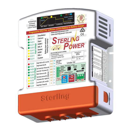
Front Panel Display
Front Label Display Annotated
Explains the meaning of labels and indicators on the unit's front panel.
Auxiliary Information LEDs
Describes additional LEDs that provide operational status and warnings.
Front Panel Details and Specifications
Under Lid Components
Identifies internal components and connection points found under the unit's lid.
Cable and Fuse Guidelines
Provides recommended cable sizes and fuse ratings for installation.
Unit Dimensions
Lists the physical dimensions of the battery charger unit.
Installation Diagrams (Non-Solar)
Temperature Sensor Installation
Details how to connect and the function of the optional temperature sensor.
BMS Connector Operations
Explains how to connect Battery Management System (BMS) signals for shutdown.
Remote Voltage Sense Connection
Describes how to connect the remote voltage sense for accurate battery charging.
Lithium Battery Installation
Changing Battery Type for Lithium
Guides on selecting appropriate lithium battery presets or custom profiles.
External BMS Shutdown Procedure
Explains how to use external BMS signals to control the charger.
Internal BMS Shutdown and 0 Deg C Trip
Covers internal BMS functions and setting a low-temperature trip point.
Automatic and Ignition Feed Modes
Automatic Activation Mode
Details the default mode where charging is based on input voltage sensing.
2x Ignition Feed Modes Explained
Describes two modes that use the ignition signal for charger control.
Initial Setup and Operation
First Time Use Guide
Provides initial steps for connecting and preparing the unit for operation.
Button Operation Guide
Explains how to use the buttons for navigation and setting adjustments.
Factory Reset Procedure
Details how to restore the unit to its default factory settings.
Button and Control Functions
Button Function Table
A comprehensive table mapping button presses to specific functions and modes.
Factory Reset Confirmation
Explains how to confirm a successful factory reset.
Advanced Force Options
Silence Buzzer and Software Version
Options to silence audible alarms and view software version.
Battery Type Select and Live Output
Functions to select battery types and force live output without a battery.
Ignition Feed Mode and Operational Voltages
Setting ignition feed modes and adjusting activation/deactivation voltages.
Braking Timer and Temperature Compensation
Configuring regenerative braking timer and temperature voltage compensation.
Buzzer Off and Maintenance Mode
Options to permanently disable the buzzer or enter maintenance mode.
Further Force Options
Float Mode and 1/2 Power Mode
Forcing the unit into float mode or half power mode.
Night Mode and Standby Mode
Activating night mode for reduced power or standby mode.
Turn Charger Off and OEM Lock
Functions to turn the charger off or lock settings via OEM lock.
Solar/BB Charger On/Off Control
Allows turning the solar or BB charger functions on or off individually.
Custom Settings
Custom Battery Type Setting
Detailed guide for expert users to create custom charging profiles.
Adjusting Charge Voltages
Steps to adjust boost, conditioning, and float voltages for custom profiles.
Adjusting Absorption Time Factor
How to adjust the absorption time multiplier for battery charging.
Absorption Time Factor Explanation
Explains the purpose and calculation method of the Absorption Time Factor.
Adjusting Absorption Time
Setting minimum and maximum absorption times for custom profiles.
Custom Settings Continuation
Adjusting Maximum Absorption Time
Final adjustment for maximum absorption time within custom profiles.
Adjusting Operational Voltages Linked
Explains how cut-off voltage adjustment affects all other voltages.
Temperature Sensor Trip Adjustment
Setting a specific temperature trip point for charger shutdown.
Remote Control Operations
Remote Control Button Functions
Details the functions of buttons on the remote control unit.
Menu Navigation and Options
Guides on accessing and navigating the remote control's menu system.
Remote Error Codes
Lists and explains error codes displayed on the remote control.
Understanding LED Information Panel
LED Zone Breakdown
Explains the different zones of LEDs on the front panel and their purposes.
LED Voltage Reading Examples
Illustrates how to interpret LED patterns for input and output voltages.
Solar Panel Zone Operation
Describes the function of Zone 4 LEDs specifically for solar operation.
Fault Finding and Troubleshooting
Basic Testing Procedure
Outlines steps to test the battery charger's functionality and charging process.
Output Voltage Issues
Diagnoses common problems related to low or incorrect output voltage.
Input Voltage Issues
Identifies causes for low input voltage and potential alternator issues.
LED Fault Indicators
Explains specific LED patterns indicating faults, over-voltage, and temperature issues.
Need help?
Do you have a question about the BBS1230 and is the answer not in the manual?
Questions and answers