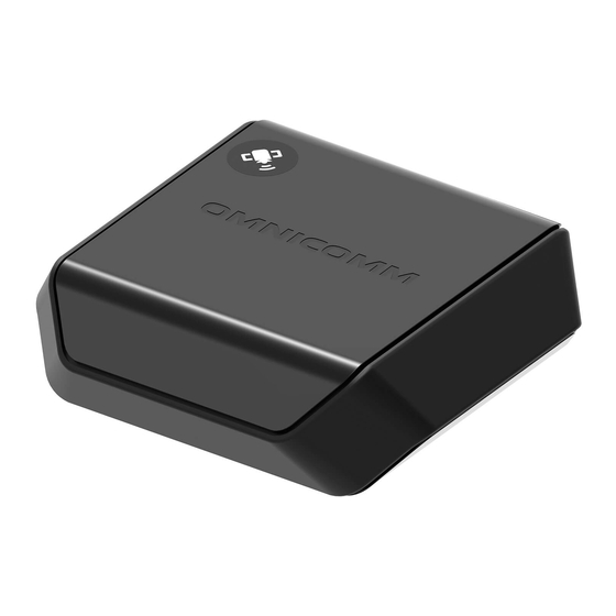
Table of Contents
Advertisement
Advertisement
Table of Contents

Summarization of Contents
General Information
Attention
Observe safety rules and regulatory requirements during installation.
Technical Specifications
Interfaces
Details communication, I/O, and built-in interfaces of the terminals.
Design and Capabilities
Covers physical dimensions, operating temperature, antenna design, and overall capabilities.
Installation Guide
SIM Card Installation
Step-by-step instructions for inserting the SIM card into the terminal.
Wire Color Designation
Defines wire colors for Omnicomm Smart and Light terminals' connections.
Power and Ignition Connection
Diagrams illustrate connecting terminals for power supply and ignition key.
Terminal Configuration
Terminal Placement
Recommendations for installing the terminal inside the vehicle for optimal performance.
Omnicomm Configurator Usage
Guide to using the Omnicomm Configurator software for terminal setup.
Operation Parameters
Remote Configuration Server (RCS)
Instructions for accessing and using the RCS for remote terminal configuration.
GPRS and Server Connection
Configuring GPRS connection and linking terminals to communication servers.
Data Collection Settings
Parameters for managing data collection timing, modes, and intervals.
Ignition and Speed Sources
Selecting data sources for ignition status and vehicle speed.
Driving Safety Features
Configuration of Engine RPM monitoring and dangerous driving controls.
Tampering and Jamming Detection
Settings for body tampering detection and signal jamming alerts.
Service Functions
Terminal Management
Covers terminal reboot and password protection for configuration changes.
Data Flow Control
How to block/unblock data collection and transmission, and RCS password settings.
Auxiliary Equipment
RS-485 Interface
Connecting auxiliary equipment via RS-485 interface.
Fuel Level Sensors
Detailed setup and connection for various fuel level sensors.
Omnicomm Displays and Indicators
Setup for ICON display and LLD indicator.
CAN-LOG Controllers
Instructions for connecting CAN-LOG controllers to the terminal.
Universal Inputs
Configuring universal inputs for various sensor types.
Driver Identification
Methods and settings for identifying drivers using cards or keys.
Controlled Outputs
Setting operation rules for outputs based on events and states.
Geofence Settings
Configuration of geofences to enable controlled outputs.
Panic Button
Configuration and connection of the panic button.
CAN Bus Data Integration
Reading and configuring vehicle parameters from the CAN bus.
Status Notifications and Commands
LED and Sound Indicators
Interpreting LED signals and sound alerts for terminal status.
SMS Command Reference
List of SMS commands for terminal management and status retrieval.
Terminal Event SMS Alerts
Formats and examples of SMS messages sent by the terminal for events.
Firmware Information
Firmware Change Log
Records of changes and fixes implemented in firmware updates.


Need help?
Do you have a question about the Light and is the answer not in the manual?
Questions and answers