Sign In
Upload
Download
Table of Contents
Contents
Add to my manuals
Delete from my manuals
Share
URL of this page:
HTML Link:
Bookmark this page
Add
Manual will be automatically added to "My Manuals"
Print this page
×
Bookmark added
×
Added to my manuals
Manuals
Brands
OKM Manuals
Security Sensors
GeoSeeker
User manual
OKM GeoSeeker User Manual
Hide thumbs
1
2
Table Of Contents
3
4
5
6
7
8
9
10
11
12
13
14
15
16
17
18
19
20
21
22
23
24
25
26
27
28
29
30
31
32
33
34
35
36
37
38
39
40
41
42
43
44
45
46
47
48
49
50
51
52
53
54
55
56
57
58
59
60
61
62
63
64
65
66
67
68
69
70
71
72
page
of
72
Go
/
72
Contents
Table of Contents
Bookmarks
Table of Contents
Table of Contents
1 Introduction
Preface
Important Notes
Security Guidelines
General Notes
Surrounding Area
Voltage / Power Supply
Maintenance and Services
Danger of Explosion During Excavation
2 Technical Specifications
Controller (Receiving Unit)
Power Box (Sending Unit)
Electrodes
Cable Drums
Power Drum (Ø 290 MM)
Voltage Drum (Ø 100 MM)
Tablet PC, Minimum Requirements
3 Scope of Delivery
4 Control Elements
Electrodes
Cable Drums
Power Cable Drums (Ø 290 MM)
Figure 4.1: Elements of the Electrodes
Voltage Cable Drums (Ø 120 MM)
Figure 4.2: Elements of the Power Cable Drums
Controller
Figure 4.3: Elements of the Voltage Cable Drums
Figure 4.4: Control Elements of the Controller
Tablet Holder
Power Box
Figure 4.5: Elements of the Tablet Holder
Figure 4.6: Control Elements of the Power Box
5 Android Application
Download & Installation
Figure 5.1: Installation of the Application Via Google Play Store
Operating Modes and Functionality
New Measurement
Figure 5.2: Application's Main Menu
Figure 5.3: New Measurement - Creation Process
Figure 5.4: New Measurement - Project Title / Notes
Figure 5.5: New Measurement - Scan Mode
Figure 5.6: New Measurement - Scan Profile
Figure 5.7: New Measurement - Depth Settings
Figure 5.8: New Measurement - Field Dimensions
Figure 5.9: New Measurement - Arrangement of Electrodes
Continue Measurement
Figure 5.10: Continue Measurement
View Measurement
Figure 5.11: View Measurement - List of Files
Figure 5.12: View Measurement - 3D Representation
Activation
Figure 5.13: Activation
Support Information
Figure 5.14: Support Information
6 Preparing and Maintaining the Equipment
Preparing the Controller
Placing and Charging the Batteries
Figure 6.1: Placing Batteries into the Controller's Compartments
Mounting the Tablet PC Holder
Figure 6.2: Connecting the Controller's Charger
Mounting the Voltage Cable Drums
Figure 6.3: Tablet PC Mounted to Controller
Figure 6.4: Voltage Cable Drums Mounted to Controller
Preparing the Power Box
Charging the Internal Batteries
Figure 6.5: Connecting the Power Box Charger
Creating a Wi-Fi Connection
Figure 6.6: Enabling Wi-Fi
Figure 6.7: Entering Wi-Fi Password
7 Conducting a Measurement
Basic Information
Figure 7.1: Detection of Thick Objects Is Better than Flat Objects
General Measurement Procedure
Figure 7.2: Dividing the Field into Scan Points and Setting up Markers
Figure 7.3: Power Injection Depth Depends on Electrodes Distance
Figure 7.4: Available Scan Modes
Figure 7.5: Instruction Screen for Setting up a Measurement
Setting up a Measurement
Setting up Your Scan Field with Markers
Setting up the Power Injection for Active Scan Modes
Setting up the Voltage Measurement
Final Connection Schemas
Active Scan (Accurate)
Active Scan (Quick)
Figure 7.6: Arrangement of Electrodes During Active Scan (Accurate)
Passive Scan
Figure 7.7: Arrangement of Electrodes During Active Scan (Quick)
Figure 7.8: Arrangement of Electrodes During Passive Scan
8 Analyzing a Measurement
Interpretation of Scan Values
Figure 8.1: Measure Values as Indicated During a Measurement
Interpretation of Graphical Representations
Active Scan
Figure 8.2: Graphical 3D Representation of an Active Scan
Passive Scan
Figure 8.3: Graphical 3D Representation of a Passive Scan
Examples
Passive Measurement
Active Measurements
Water Deposits
Figure 8.4: Example of a Passive Measurement - Flowing Water
Figure 8.5: Example of an Active Measurement - Water Deposit
Water Deposits with Areas of High Resistivity
Cavities
Figure 8.6: Example of an Active Measurement - Water Deposit and Barrier
Figure 8.7: Example of an Active Measurement - Cavity
Impervious Layers
Figure 8.8: Example of an Active Measurement - Impervious Layer / Barrier
9 Tips and Tricks
Improving Your Scan Results
Speeding up Your Measurement
Figure 9.1: Electrodes Need Good Electrical Ground Contact
Figure 9.2: Electrodes Have to be Equally Set into the Ground
Figure 9.3: Operating the Geoseeker with 3 People
Figure 9.4: Operating the Geoseeker with 5 People
Operation with 3 People
Operation with 5 People
Measurements under Tough Soil Conditions
Figure 9.5: Drilling a Hole and Refilling It for the Electrode
Advertisement
Quick Links
Download this manual
FS Future Series
®
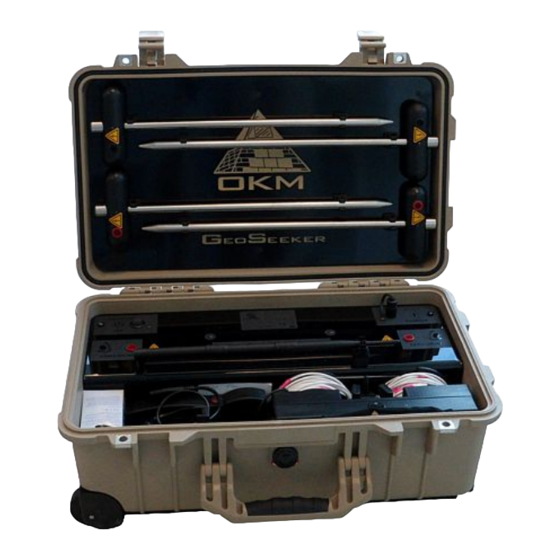
GeoSeeker
User's Manual
Table of
Contents
Previous
Page
Next
Page
1
2
3
4
5
Advertisement
Table of Contents
Need help?
Do you have a question about the GeoSeeker and is the answer not in the manual?
Ask a question
Questions and answers
Related Manuals for OKM GeoSeeker
Security Sensors OKM FS Future Series User Manual
(72 pages)
Security Sensors OKM eXp 4500 User Manual
Fs future series (94 pages)
Security Sensors OKM Future Series User Manual
(64 pages)
Security Sensors OKM Delta Ranger DR-A01 User Manual
Detector for treasure, gold and cavity hunt (32 pages)
Security Sensors OKM DELTA RANGER Quick Start Manual
(4 pages)
Security Sensors OKM Delta Ranger User Manual
Detector for treasure, gold and cavity hunt (62 pages)
Table of Contents
Print
Rename the bookmark
Delete bookmark?
Delete from my manuals?
Login
Sign In
OR
Sign in with Facebook
Sign in with Google
Upload manual
Upload from disk
Upload from URL


Need help?
Do you have a question about the GeoSeeker and is the answer not in the manual?
Questions and answers