Advertisement
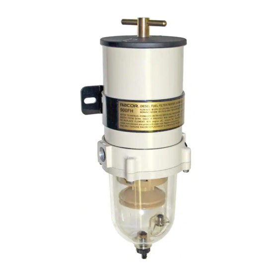
Turbine Series
900FH and 1000FH
Fuel Filter/Water Separators
Instruction Part Number 12960 Rev E
Turbine Series filters protect
precision engine components
from dirt, rust, algae, asphaltines,
varnishes, and especially water,
which is prevalent in engine fuels.
They remove contaminants from
fuel using the following legendary
three stage process:
Stage 1 - Separation
As fuel enters the assembly, it
moves through the centrifuge and
spins off large solids and water
droplets, which are heavier than
fuel, and fall to the bottom of the
collection bowl.
Stage 2 - Coalescing
Small water droplets bead-up on
the surface of the conical baffle
and cartridge filter. When heavy
enough, they too fall to the bottom
of the collection bowl.
Stage 3 - Filtration
®
Proprietary Aquabloc
filters repel water and remove
contaminants from fuel down to
2 micron (nominal). Aquabloc
cartridge filters are waterproof
and effective longer than water
absorbing filters.
Getting Started
cartridge
The following customer supplied
materials should be on-hand
before beginning installation.
• Shop Towels
• Diesel Fuel (about 1 gallon)
• Thread Sealant (no thread
tapes)
• Parker Super O-Lube
(RK 31605) or equivalent
• Fuel Hose
• Mounting Hardware (3/8˝
or M10 fasteners)
• Inlet/Outlet Fittings
Contact Information
Parker Hannifin Corporation
Racor Division
P.O. Box 3208
3400 Finch Road
Modesto, CA 95353
phone 800 344 3286
209 521 7860
fax 209 529 3278
racor@parker.com
parker.com/racor
Advertisement
Table of Contents

Related Manuals for Parker Racor 1000FH


Summarization of Contents
Turbine Series Product Description
Stage 1 - Separation
Fuel is spun via centrifuge, separating solids and water to the collection bowl.
Stage 2 - Coalescing
Water droplets gather on the baffle and filter, then fall to the collection bowl.
Stage 3 - Filtration
Proprietary Aquabloc filters repel water and remove contaminants down to 2 microns.
Installation Diagram Overview
Optional Bypass Installation
Describes valve operation for servicing the filter without engine shutdown.
Optional Vacuum Gauge
Aids in monitoring system restriction and filter element life.
Installation Instructions
Before Installation
Key safety and preparation steps before commencing the installation process.
Positioning Filter
Guidance on optimal placement of the filter for efficient water separation.
Installing Filter
Steps for correctly installing the filter, including hose routing and restrictions.
Priming Instructions
Procedure for filling the filter with fuel and preparing it for engine operation.
Service Instructions
Draining Water
Procedure for regularly draining accumulated water from the collection bowl.
Vacuum Side Applications
Specific steps for draining water in vacuum side fuel system installations.
Pressure Side Applications
Specific steps for draining water in pressure side fuel system installations.
Installing Optional In-Filter Heater
Heater Wiring Installation
Crucial safety and installation steps for wiring the in-filter heater.
Troubleshooting
Filter Safety Valve
Guidance on the filter safety valve, including O-ring condition and tightening.
Common Issues and Solutions
Advice on air leaks, drain issues, and sensor functionality for optimal performance.
Troubleshooting Continued
Fuel System and Filter Application
Ensuring correct fuel system application and filter specifications for engine performance.
Heater Operation and Testing
Information on in-filter heater functionality, power requirements, and testing procedures.
Need help?
Do you have a question about the Racor 1000FH and is the answer not in the manual?
Questions and answers