Table of Contents
Advertisement
Quick Links
SITRANS F
Electromagnetic flowmeters
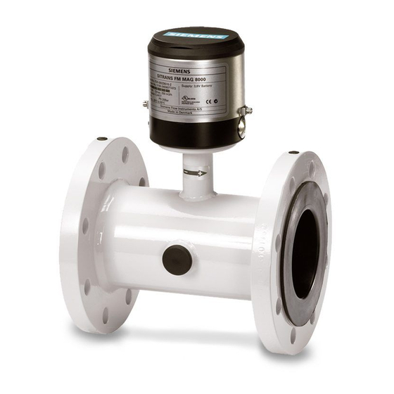
SITRANS FM MAG 8000
Operating Instructions
7ME681. MAG 8000
7ME682. MAG 8000 CT
03/2020
A5E03071515-AH
Introduction
Safety notes
Description
Installing/Mounting
Connecting
Commissioning
Operating
Service and maintenance
Diagnostics and
Troubleshooting
Technical data
Product documentation and
support
Spare parts/Accessories
Flow Tool
Qualification certificate
Unit conversion table
Parameter lists
Sizing sensor
Features
1
2
3
4
5
6
7
8
9
10
A
B
C
D
E
F
G
H
Advertisement
Table of Contents

Related Manuals for Siemens 7ME6810


Summarization of Contents
Legal Information
Warning Notice System
Explains the manual's warning notice system for safety and property damage.
Qualified Personnel
Defines the qualifications required for operating the product.
Proper Use of Siemens Products
Outlines guidelines for the correct and safe usage of Siemens products.
Trademarks
Lists registered and used trademarks within the publication.
Disclaimer of Liability
States the terms and limitations of liability for the publication's content.
Introduction
Purpose of this Documentation
Details the manual's objective to provide information for commissioning and use.
Items Supplied
Lists the components included in the product delivery.
Document History
Tracks revisions and changes made to the documentation over time.
Checking the Consignment
Provides steps for verifying the delivered items against the order.
Security Information
Highlights industrial security functions and customer responsibilities for cyber threats.
Transportation and Storage
Gives guidelines for protecting the device during transport and storage.
Notes on Warranty
Clarifies warranty conditions and the manual's relation to sales contracts.
Safety Notes
General Safety Instructions
Provides essential safety precautions for installation and operation.
Laws and Directives
Lists applicable safety rules, provisions, and laws for connection and operation.
Conformity with European Directives
Explains the meaning of CE marking and related European directives.
Lithium Batteries
Details potential hazards and precautions when handling lithium batteries.
Installation in Hazardous Area
States that the device is not approved for use in hazardous areas.
Description
System Components
Describes the main parts of the SITRANS F M MAG 8000 water meter system.
Operating Principle
Explains how the MAG 8000 water meter functions and processes flow data.
Design
Illustrates the physical design of the MAG 8000 water meter, including compact and remote versions.
Benefits
Lists the key advantages and features of the MAG 8000 water meter.
Installing/Mounting
General Information
Introduces the chapter on installing the water meter in compact and remote versions.
Sensor Installation
Details the three-step process for installing the flow meter sensor.
Potential Equalization
Explains how liquid potential equalization or grounding is achieved.
Grounding
Describes methods for grounding the sensor body for signal protection.
Cathodic-Protected Pipes
Advises on meter installation in cathodic-protected pipes.
Potting and Direct Burial
Covers procedures for potting the transmitter and direct burial of the remote sensor.
Transmitter Installation
Guides on mounting the transmitter bracket on walls or pipes.
MAG 8000 CT
Covers specific installation aspects for the MAG 8000 CT version, including sealing.
Installation Conditions
Details installation requirements, specifically for the MID option (MI-001).
Connecting
General Safety Requirements
Outlines essential safety regulations for electrical installation of the device.
Remote Version
Explains the procedures for remote sensor and transmitter installation.
Power Supply
Details connection diagrams and wiring for AC/DC and battery power supplies.
Outputs
Describes pulse output connection diagrams and configuration options.
Communication Modules
Covers connection diagrams for RS 232 and RS 485 communication modules.
Connection of Add-on Modules
Explains how to connect various add-on communication modules.
Commissioning
Overview SIMATIC PDM
Introduces SIMATIC PDM as a tool for device configuration and maintenance.
Initial Commissioning via SIMATIC PDM
Guides through the process of checking PDM version and updating device descriptions.
Configuring the Device
Describes how to set up the meter for communication with a PC using PDM.
Setting the Basic Parameters
Explains how to set fundamental parameters and manage device data via PDM.
Unit Selection
Details how to change the totalizer and flow rate units for the device.
Output Configuration
Explains how to configure pulse outputs for volume, alarm, or call-up functions.
Data Protection
Describes how to protect device parameters using a hardware key.
Operating
Operation via Key and Display
Explains how to interact with the meter using the physical key and display interface.
Display Symbols
Details the meaning of various symbols shown on the device's status bar.
Default Display Information and Accessible Display Menus
Defines default display content and accessible menus via parameter settings.
Operator Menu
Describes the structure and content of the operator menu, including indexes for data.
Internal Data Handling
Explains how the meter handles internal data, including meter status.
Data Logger / Consumption Alarm
Covers the integrated data logger and consumption alarm features of the device.
Battery-Powered Operation
Details battery status, consumption calculation, and operation time.
Service and Maintenance
Maintenance
Outlines periodic inspection requirements for the device.
MAG 8000 Service Guidelines
Provides guidance on detecting and solving common meter performance and fault issues.
Replacing Transmitter or PCB Board
Explains the procedures and options for replacing the transmitter or PCB board.
Battery Replacement
Provides a step-by-step guide for replacing the device's battery pack.
Power Up with Battery Reset, Date and Time Set Up
Describes the power-up procedure after battery replacement for setting date and time.
Verification Mode
Explains how to enable and use verification mode for calibration time reduction.
Transport
Provides notices regarding the transport of the device, especially with a fitted battery.
Return Procedure
Outlines the necessary steps and documentation for returning the device.
Disposal
Details guidelines for the proper recycling and disposal of the device and its components.
Battery Disposal
Specifies regulations and procedures for disposing of batteries.
Diagnostics and Troubleshooting
Fault Codes
Lists and describes various fault codes, their causes, and remedies.
Built-in Functions
Details built-in functions like empty pipe detection, insulation test, and coil-current test.
Flow Simulation
Explains the use of the built-in flow simulator for verification and adjustment.
Technical Data
MAG 8000 Water Meter
Provides technical specifications for the MAG 8000 water meter, including accuracy and approvals.
Sensor
Lists technical specifications for the sensor, such as size, flange range, and excitation frequency.
Transmitter
Details specifications for the transmitter, including installation, material, and display.
Power Supply
Covers technical data related to internal and external battery and mains power supplies.
Modbus RTU
Provides the Modbus RTU specification for add-on modules.
Output Characteristics
Describes the behavior and configuration of the device's pulse and alarm outputs.
Meter Uncertainty
Explains how meter uncertainty is determined and calibration is conducted.
FM Fire Service Applications (MAG 8000 and MAG 8000 CT)
Details FM Fire Service approval and applicable sizes for fire protection systems.
MAG 8000 CT (7ME6820) (Revenue program) Water Meter Type Approval
Covers type approval information for the MAG 8000 CT under OIML R49:2013 standard.
MAG 8000 CT (7ME6820) (Revenue program) MID Option (MI-001)
Details MID option (MI-001) type approval for the MAG 8000 CT.
The Effect of Temperature MAG 8000 (7ME6810) and MAG 8000 CT (7ME6820)
Shows how temperature affects pressure ratings for different flange specifications.
Dimension Drawings
Provides dimensional drawings and tables for meter and flange dimensions.
Product Documentation and Support
Product Documentation
Lists available formats and sources for product documentation, including online portals.
Technical Support
Provides information on how to obtain technical support and find contact details.
Spare Parts/Accessories
Ordering of Spare Parts
Guides users on how to obtain the latest ordering data for spare parts.
Flow Tool
Flow Tool
Describes the Flow Tool software requirements and download sources.
Initial Commissioning via Flow Tool
Explains how to start the commissioning process using Flow Tool software.
Configuring the Device
Details the steps for setting up the meter for PC communication using Flow Tool.
Setting the Basic Parameters
Covers parameter settings and data management within the Flow Tool software.
Unit Selection
Explains how to select and configure measurement units within Flow Tool.
Output Configuration
Guides on configuring pulse outputs using the Flow Tool software.
Default Display Information and Accessible Display Menus
Defines display settings and accessible menus configurable via Flow Tool.
Internal Data Handling
Describes data logging and meter status monitoring within Flow Tool.
Battery Configuration
Details how to configure battery settings and power management using Flow Tool.
Qualification Certificate
Commissioning
Outlines the steps for generating a qualification certificate from PDM.
Enabling Insulation Test
Details the procedure for enabling the insulation test prior to certificate generation.
Uploading the Device Data to the PC
Explains how to upload device parameters to a PC for analysis.
Generating the Qualification Certificate
Guides on the process of generating the qualification certificate using PDM.
Result Evaluation
Describes how service technicians evaluate the device parameters against reference values.
Unit Conversion Table
Totalizer / Volume Unit (Parameter 8)
Lists totalizer units and their corresponding correction factors for parameter 300.
Flow Rate Unit (Parameter 9)
Lists flow rate units and their corresponding correction factors for parameter 301.
Parameter Lists
1-99
Lists parameters from 1 to 99, including their ID, version, view, type, settings, and range.
100-199
Lists parameters from 100 to 199, detailing their configuration and data ranges.
200-299
Lists parameters from 200 to 299, focusing on fault and alarm configurations.
300-399
Lists parameters from 300 to 399, covering unit settings and physical properties.
400-499
Lists parameters from 400 to 499, related to output configuration and device communication.
500-599
Lists parameters from 500 to 599, covering battery, power, and diagnostic functions.
600-799
Lists parameters from 600 to 799, related to data logging intervals and status.
800-899
Lists parameters from 800 to 899, covering insulation test, leakage detection, and tariff settings.
Sizing Sensor
Sizing Table DN 25 to 1200 (1" to 48")
Provides a table relating flow velocity, quantity, and sensor dimension for selection.
Guidelines for Selection of Sensor
Offers recommendations for selecting the appropriate sensor based on measuring ranges.
Features
Application Identification
Describes how to identify the application and meter location with tag numbers.
Time and Date
Explains the real-time clock and date functionality and its drift.
Totalizer
Details the three totalizer functions, including bidirectional netflow and selectable start values.
Measurement
Covers selectable units, excitation frequency, and data logger functions.
Alarm
Explains alarm indications, monitoring, fatal faults, and warning conditions.
Meter Status
Monitors important revenue parameters and data changes like totalizers and tariffs.
Data Protection
Describes data backup, password protection, and hardware protection mechanisms.
Battery Power Management
Details optimal battery information, capacity calculation, and power management.
Diagnostic
Lists continuous self-tests and diagnostic features, including advanced version functions.
Insulation Test
Explains the insulation test for signal immunity against disturbances.
Leakage Detection (Advanced Version Only)
Describes monitoring flow during time windows to detect leakage.
Need help?
Do you have a question about the 7ME6810 and is the answer not in the manual?
Questions and answers