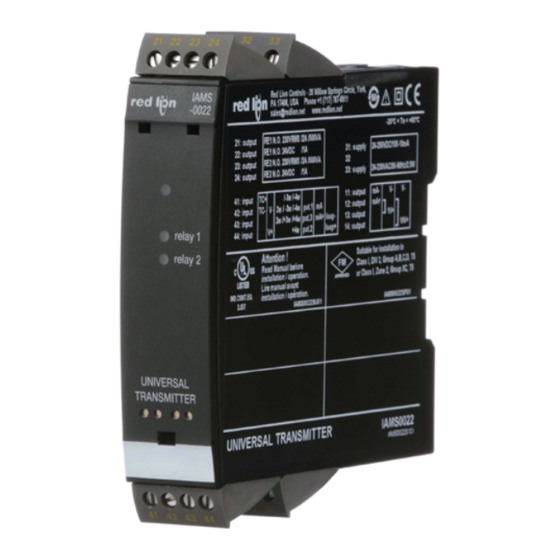
Summarization of Contents
Safety Warnings
General Safety Precautions
Essential safety advice for operating the IAMS device.
Safety Instructions
Definitions, Environment, and Unpacking
Key terms, environmental conditions, and unpacking guidance.
Mounting Guidelines
Instructions for physically installing the device.
Operational and Installation Requirements
UL Installation and Calibration
Covers UL requirements and device calibration procedures.
Normal Operation and Cleaning
Guidelines for daily use and maintenance.
Liability Statement
Legal disclaimer for product use.
Device Handling and Error Indicators
How to Dismantle the Device
Step-by-step instructions for removing the device.
Troubleshooting AO.ER Display and Red LED
Handling specific error indicators and display messages.
Device Features and Applications
Advanced Features Overview
Highlights programmable features and diagnostics.
Key Applications and Use Cases
Describes various functionalities and deployment scenarios.
Technical Characteristics
Configuration, Indicators, and Isolation
Details on parameter modification, status LEDs, and galvanic isolation.
Vital Data Checks
Information on continuous checks of stored data for safety.
PGM Display / Programmer Front
Functionality and Ease of Use
Describes the user-friendly interface and navigation.
Application and Technical Details
Use cases and display specifications.
Mounting and Installation
Instructions for attaching the programmer.
PGMMOD Mounting and Demounting
PGMMOD Mounting Procedure
Step-by-step guide to attach the programmer module.
PGMMOD Demounting Procedure
Steps for safely removing the programmer module.
Input and Output Signal Wiring
Input Signal Connections
Diagrams showing various input signal wiring.
Output Signal and Supply Wiring
Diagrams for output signals and power supply connections.
Electrical and Mechanical Specifications
Environmental and Mechanical Specs
Operating conditions, dimensions, and weights.
Common Specifications
Details on supply, consumption, isolation, and interfaces.
Accuracy Specifications
General Accuracy Values
Overall accuracy and temperature coefficient data.
Input Type Specifications
Basic Values for Input Types
Accuracy and coefficient details for mA, Volt, Pt100, etc.
RTD and Resistance Input Details
Specifics for RTD, linear resistance, and potentiometer inputs.
Temperature and Signal Input Details
TC Sensor Type Specifications
Range and standard details for various TC types.
Current and Voltage Input Specs
Measurement ranges and error detection for current/voltage.
Output and Relay Performance
Current/Voltage Output and Limits
Details on output signal ranges, load, and limits.
Relay Functions and Certifications
Relay functions, hysteresis, delays, and observed authority requirements.
Input Signal Visualization and Error Limits
Sensor Error and Range Visualization
How errors and out-of-range signals are displayed.
Sensor Error Detection Limits
Specific limits for detecting sensor errors.
Error Indications
Hardware Error Readouts and Causes
Table of hardware errors, their codes, and causes.
Connection Diagrams
Supply and Input Wiring Diagrams
Wiring diagrams for power supply and various inputs.
Output Wiring Diagrams
Wiring diagrams for analog outputs and relays.
Block Diagram
Internal Device Architecture
Schematic showing internal components and signal flow.
Configuration and Function Key Operation
General Configuration Process
How to navigate menus and set parameters using function keys.
Setpoint Adjustment and Password Protection
Procedures for changing setpoints and securing access.
Signal and Sensor Error Display
Error Indication via Display and LEDs
How errors are shown via display and LED indicators.
Relay Function Settings
Overview of available relay function options.
Relay Function Details
Latch Function Explanation
Detailed explanation of the relay latch function and its application.
Advanced Functions and Setup
Manual Latch Deactivation
How to manually deactivate a latched relay output.
Display, Calibration, and Simulation
Settings for display, process calibration, and signal simulation.
Password and Language Settings
Options for setting passwords and selecting display language.
Auto Diagnosis
Possible Errors and Their Causes
Lists potential errors and their explanations.
Unit Selection and Memory Management
Unit Selection and Safety Readback
Choosing process units and enabling safety features.
Configuration Memory Operations
Saving and transferring device configurations.
Routing Diagram - Power Up and Input Setup
Power Up Sequence and Initial Settings
Initial device startup and parameter selection.
Input Type and Range Configuration
Setting up input signal types and ranges.
Routing Diagram - Parameter Configuration
Setpoint, Window, and Error Settings
Configuration of setpoints, windows, and error actions.
Selectable Units
List of available units for display.
Routing Diagram - Relay and Function Settings
Relay Function and Delay Settings
Configuration for relay functions, delays, and hysteresis.
Routing Diagram - Output Configuration
Output Signal Range Configuration
Setting output signal ranges for current and voltage.
Routing Diagram - Advanced Settings
Memory, Display, and Calibration Settings
Configuring memory, display, and process calibration.
Simulation, Password, and Language
Settings for simulation, password protection, and language.
Routing Diagram - Latch Function Management
Manual Latch Deactivation
Procedures to manually deactivate latched relays.
Relay Reset Procedures
Steps for resetting relay latches.
Help Text Index
Help Text for Input and Relay Functions
Index of help text descriptions for input and relay settings.
Advanced Function Index
Index of Advanced Setup Options
List of advanced functions like password, language, and calibration.
Graphic Depiction of Latch Function Setpoint
Latch Function Setpoint Behavior
Visual representation of latching with setpoints and delays.
Graphic Depiction of Latch Function Window
Latch Function Window Behavior
Visual representation of latching with window setpoints.
Graphic Depiction of Relay Action
Relay Action Setpoint Diagrams
Visuals of relay operation based on setpoints.
Relay Action Window Diagrams
Visuals of relay operation based on window settings.
Ordering Information
Product Descriptions and Part Numbers
List of device models and their corresponding part numbers.


Need help?
Do you have a question about the IAMS0020 and is the answer not in the manual?
Questions and answers