Table of Contents
Advertisement
Quick Links
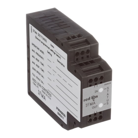
MODEL IFMA - DIN-RAIL FREQUENCY TO ANALOG CONVERTER
DESCRIPTION
The Model IFMA accepts a frequency input, and outputs an analog voltage or
current in proportion to the input frequency, with 0.1% accuracy. The full scale
input frequency can be set to any value from 1 Hz to 25 KHz, either with a
frequency source, or digitally with the on-board rotary switch and push-button.
The IFMA utilizes a seven position DIP switch, a rotary switch, a push-button
and two indication LEDs to accomplish input circuit configuration, operational
parameter set-up, and Input/Output indication. The input circuitry is DIP switch
selectable for a variety of sources.
The indication LEDs are used during normal operation to display the input
and output status of the IFMA. These LEDs are also used to provide visual
feedback to the user of the existing parameter settings during parameter set-up.
The IFMA operates in one of four output modes. The programmable minimum
and maximum response times provide optimal response at any input frequency.
The unit is equipped with a universal mounting foot for attachment to
standard DIN style mounting rails, including top hat profile rail according to EN
50 022 - 35 x7.5 and 35 x 15, and G profile rail according to EN 50 035 - G 32.
SAFETY SUMMARY
All safety related regulations, local codes and instructions that appear in the
manual or on equipment must be observed to ensure personal safety and to
prevent damage to either the instrument or equipment connected to it. If
equipment is used in a manner not specified by the manufacturer, the protection
provided by the equipment may be impaired.
SPECIFICATIONS
1. POWER:
AC Operation: 85 to 250 VAC, 48 to 62 Hz; 6.5 VA
DC Operation: 9 to 32 VDC; 2.5 W
Power Up Current: Ip = 600 mA for 50 msec. max.
2. SENSOR POWER: (AC version only) +12 VDC ±25% @ 60 mA max.
3. OPERATING FREQUENCY RANGE:
From 0 Hz to 25 KHz; user selectable.
4. SIGNAL INPUT: DIP switch selectable to accept signals from a variety of
sources, including switch contacts, outputs from CMOS or TTL circuits,
magnetic pickups, and all standard RLC sensors.
Current Sourcing: Internal 1 K pull-down resistor for sensors with current
sourcing output. (Max. sensor output current = 24 mA @ 24 V output.)
Current Sinking: Internal 3.9 K pull-up resistor for sensors with current
sinking output. (Max. sensor current = 3 mA.)
CAUTION: Risk of Danger.
Read complete instructions prior to
installation and operation of the unit.
Phone: 800.894.0412 - Fax: 888.723.4773 - Web: www.clrwtr.com - Email: info@clrwtr.com
CAUTION: Risk of electric shock.
SIMPLE ON-LINE RANGE SETTING
(Using Actual Input Signal or Signal Generator)
USER SETTABLE FULL SCALE FREQUENCY FROM
1 Hz to 25 KHz
FOUR OUTPUT OPERATING RANGES
(0 to 5 V, 0 to 10 V, 0 to 20 mA, and 4 to 20 mA)
PROGRAMMABLE INPUT CIRCUIT ACCEPTS OUTPUTS FROM A
VARIETY OF SENSORS
85 to 250 VAC and 9 to 32 VDC POWERED VERSIONS
AVAILABLE
LOW FREQUENCY CUT-OUT AND OVERRANGE INDICATION
3-WAY ELECTRICAL ISOLATION (POWER/INPUT/OUTPUT)
INPUT AND OUTPUT INDICATION LEDs
UL Recognized Component,
File # E137808
Low Bias: Input trigger levels V
sensitivity when used with magnetic pickups.
Hi Bias: Input trigger levels V
IL
Max. Input Signal: ±90 V; 2.75 mA max. (With both Current Sourcing and
Current Sinking resistors switched off.)
5. SIGNAL VOLTAGE OUTPUT (Selectable):
0 to 5 VDC @ 10 mA max.
0 to 10 VDC @ 10 mA max.
6. SIGNAL CURRENT OUTPUT (Selectable):
0 to 20 mA @ 10 VDC min.
4 to 20 mA@ 10 VDC min.
7. OUTPUT COMPLIANCE:
Voltage: 10 V across a min. 1K load (10 mA). Factory calibrated for loads
greater than 1 M.
Current: 20 mA through a max. 500 load (10 VDC).
8. ACCURACY: ±0.1% of full scale range (±0.2% for 0 to 5 VDC range).
9. RESOLUTION:
Voltage : 3.5 mV min.
Current: 5 μA min.
DIMENSIONS In inches (mm)
3.12
(79.2)
0
ORDERING INFORMATION
MODEL NO.
DESCRIPTION
IFMA
Pulse Rate to Analog Converter
For more information on Pricing, Enclosures & Panel Mount Kits refer to the
RLC Catalog or contact your local RLC distributor.
Bulletin No. IFMA-F
Drawing No. LP0340
Released 07/09
= 0.25 V, V
= 0.75 V; for increased
IL
IH
= 2.5 V, V
= 3.0 V; for logic level signals.
IH
1.08
(27.5)
IN
IFMA
OUT
PART NUMBERS FOR AVAILABLE
SUPPLY VOLTAGES
9 to 32 VDC
85 to 250 VAC
IFMA0035
IFMA0065
S
T
A
T
U
S
Advertisement
Table of Contents

Subscribe to Our Youtube Channel
Related Manuals for red lion IFMA0035


Summary of Contents for red lion IFMA0035
-
Page 1: Safety Summary
SUPPLY VOLTAGES 9 to 32 VDC 85 to 250 VAC IFMA Pulse Rate to Analog Converter IFMA0035 IFMA0065 CAUTION: Risk of Danger. CAUTION: Risk of electric shock. Read complete instructions prior to For more information on Pricing, Enclosures & Panel Mount Kits refer to the installation and operation of the unit. - Page 2 SPECIFICATIONS (Cont’d) EN 61000-4-4 - Electrical fast transient/burst (EFT) EN 61000-4-8 - Power frequency magnetic field 10. RESPONSE TIME: 5 msec +1 period to 10 sec +1 period; user selectable Notes: 11. INPUT IMPEDANCE: 33 K min. with the sink and source DIP switches 1.
- Page 3 EMC INSTALLATION GUIDELINES POWER AND OUTPUT CONNECTIONS Although this unit is designed with a high degree of immunity to AC Power ElectroMagnetic Interference (EMI), proper installation and wiring methods Primary AC power is connected to terminals 10 and 12 (labeled AC). For best must be followed to ensure compatibility in each application.
- Page 4 INPUT CIRCUITS, SENSOR CONNECTIONS AND CONFIGURATION SWITCH SET-UP The Model IFMA uses a comparator amplifier connected as a Schmidt S2 - ON: For logic level signals. Sets the input bias levels to V = 2.5 V, V trigger circuit to convert the input wave form into the pulse form required for = 3.0 V.
- Page 5 OUTPUT INDICATION Over range on the output : The Output LED (red) turns on and the FACTORY SETTINGS Output is “clamped” at the maximum level. Parameter Setting Value Low Frequency Cut-Out : The Output LED (red) turns on to Operating Mode 4 to 20 mA Input Range 10.000...
- Page 6 3.0 Input Range Setting Using The Rotary Switch 3.1 Place DIP switch 4 to the ON(up) position and DIP switches 5, 6, and 7 as shown. GREEN INPUT 3.2 The Green input LED blinks the existing Input Range setting, pauses and repeats. Six full digits BLINKS of numerical information blink with a short pause between digits and a longer pause at the end, Step 3.1...
- Page 7 5.0 Maximum Response Time Setting (Low Frequency Cut-Out Setting) 5.1 Place DIP switch 4 to the ON (up) position and DIP switches 5, 6, and 7 as shown. 5.2 The Green input LED blinks the corresponding Maximum Response Time Setting (see GREEN INPUT following list), pauses and repeats.
-
Page 8: Troubleshooting
6.0 Calibration (Cont’d) 6.3 Press the push-button to enable the rotary switch. The Green input LED now blinks at a faster rate, indicating that calibration values are accessible. PUSH-BUTTON 6.4 Turn rotary switch to appropriate numerical setting for calibration (see list in Step 6.0), while monitoring the output signal.
Need help?
Do you have a question about the IFMA0035 and is the answer not in the manual?
Questions and answers