Table of Contents
Advertisement
Advertisement
Table of Contents

Related Manuals for Panasonic MBDJT2207


Summarization of Contents
Model Designation Codes
Driver Model Designation
Explains the model designation code for the driver unit.
Motor Model Designation
Details the model designation code for the motor unit.
Key Capabilities
Performance and Stability
Highlights quick and stable operation, vibration, and noise reduction.
Product Accessories
Lists available accessory software and CAD data.
Product Advantages
High Response and Intelligence
Covers high response characteristics and intelligent control features like auto-gain tuning.
Compact Design and Ease of Use
Focuses on compact design and user-friendly setup features.
Appearance and Part Names
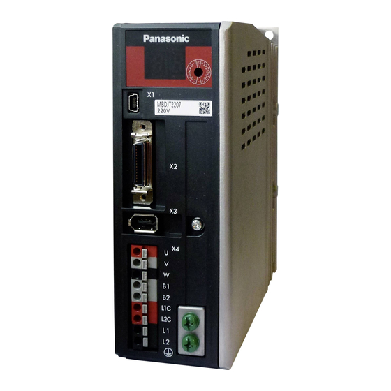
220V Size B Appearance
Illustrates the physical appearance and part names for the 220V Size B model.
220V Size C Appearance
Illustrates the physical appearance and part names for the 220V Size C model.
Connector Configuration
USB Connector (X1)
Details USB interface operations and pin configuration.
I/O Connector (X2)
Describes common digital inputs and their functionality.
Encoder Connector (X3)
Details the encoder connector pin assignment and output.
Motor and Power Connector (X4)
Describes motor connection, power supply input, and grounding for 200V system.
Input/Output Signal Interface and Functions
Multi-function Input Allocation
Explains functions assignable to multi-function inputs and their default settings.
Input Signal Parameterization
Details parameters for input signal selection and available function assignments.
Command Pulse and Output Signals
Describes command pulse input terminals and common output signals.
Multi-function Output Allocation
Explains functions assignable to multi-function outputs and their default settings.
Other Connections and Function Assignments
Details power, ground connections and output function number assignments.
Signal Interface Diagrams
Illustrates various input and output signal interface circuits.
Parameter Class 0: Basic Setup
Rotational Direction and Auto Tuning
Configures rotational direction and sets up action modes for real-time auto-gain tuning.
Command Pulse and Torque Settings
Covers command pulse settings and torque limit configuration.
Deviation and Regenerative Resistor Setup
Configures position deviation limits and external regenerative resistor usage.
Parameter Class 1: Loop Tuning
Primary Loop Gains and Filters
Sets gains and filters for the 1st position and velocity control loops.
Secondary Loop and Feed Forward Control
Configures secondary gains, filters, and feed forward parameters.
Parameter Class 2: Vibration and Noise Filtering
Notch Filter Configuration
Sets frequencies, widths, and depths for multiple notch filters.
Damping and Positional Command Filters
Configures damping filters and positional command smoothing/FIR filters.
Parameter Class 4: Input/Output Signal Configuration
Input Signal Assignment
Assigns functions to multi-function input signals (SI1-SI6).
Output Signal Assignment and Functions
Assigns functions to output signals (SO1-SO3) and configures their states.
Alarm and Warning Settings
Sets up mechanical brake actions, warning outputs, and alarm conditions.
Parameter Class 5: Advanced Settings
Electronic Gear and Pulse Output
Configures electronic gear numerator/denominator and pulse output division.
Over-travel Inhibit and Sequence Settings
Configures over-travel inhibit and various sequence and limit settings.
Torque Limit and Command Pulse Setup
Selects torque limiting methods and sets maximum command pulse input.
Parameter Class 6: Performance Optimization
Velocity Deviation and Gain Settings
Configures velocity deviation excess, position gain valid time, and scaling factor.
Alarm Response and Tuning Speed
Sets alarm response times, tuning estimation speed, and warning mask.
Need help?
Do you have a question about the MBDJT2207 and is the answer not in the manual?
Questions and answers