Table of Contents
Advertisement
Quick Links
New Product
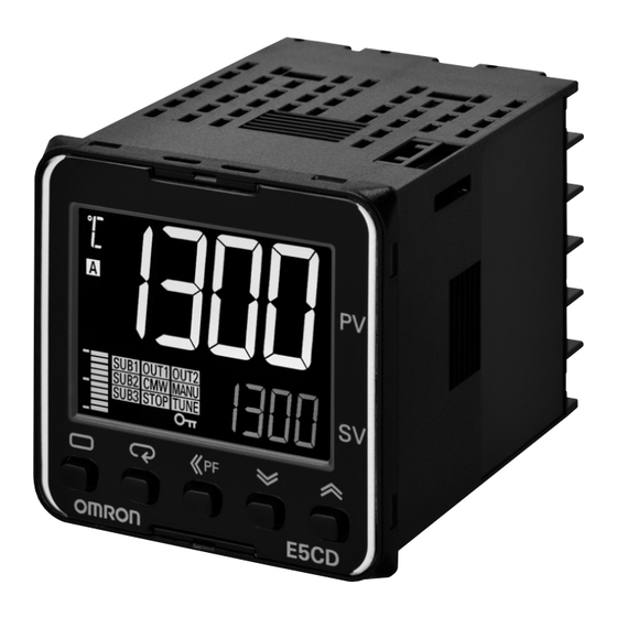
Digital Temperature Controller (Simple Type)
E5CD-800/E5ED-800
Next Generation
Digital Temperature Controllers
E5CD-800 (48 × 48 mm) and E5ED-800 (48 × 96 mm)
Optimize Control by Detecting Status Changes.
Easily Satisfy Both Productivity and Quality.
48 × 48 mm
E5CD-800
Accurately Measure Seal Temperatures
Temperature Sensors for Packaging Machines
48 × 96 mm
E5ED-800
Temperature
Sensors
E52
1
Advertisement
Table of Contents

Related Manuals for Omron E5ED-800


Summary of Contents for Omron E5ED-800
- Page 1 Digital Temperature Controller (Simple Type) E5CD-800/E5ED-800 Next Generation Digital Temperature Controllers E5CD-800 (48 × 48 mm) and E5ED-800 (48 × 96 mm) Optimize Control by Detecting Status Changes. Easily Satisfy Both Productivity and Quality. 48 × 48 mm 48 × 96 mm...
-
Page 2: Output Adjustment)
• Basic performance is same as the E5C-800 standard models. • Draw-out structure for easy maintenance. For the most recent information on models that have been certified for safety standards, refer to your OMRON website. Refer to Safety Precautions on 39. Main I/O Functions... -
Page 3: Heating And Cooling Control
E5CD-800 Model Number Legend and Standard Models Model Number Legend E5CD-@@ 2 @ D M -@@@ (Example: E5CD-RX2ADM-800) −− − − − − −−− B C D E No. of Power Model Meaning Control outputs Terminal Input auxiliary supply Options... - Page 4 E5CD-800 Optional Products (Order Separately) Terminal Covers Front Covers Model Type Model E53-COV17 Hard Front Cover Y92A-48H E53-COV23 (3pcs) Soft Front Cover Y92A-48D Note: The E53-COV10 cannot be used. Draw-out Jig Refer to page 13 for the mounted dimensions. Model...
-
Page 5: Specifications
E5CD-800 Specifications Ratings A in model number: 100 to 240 VAC, 50/60 Hz Power supply voltage D in model number: 24 VAC, 50/60 Hz; 24 VDC Operating voltage range 85% to 110% of rated supply voltage Models with option selection of 800:5.2 VA max. at 100 to 240 VAC, and 3.1 VA max. at 24 VAC or 1.6 W max. at... -
Page 6: Input Ranges
E5CD-800 Input Ranges Thermocouple/Platinum Resistance Thermometer (Universal inputs) Sensor Platinum resistance Infrared temperature Thermocouple type thermometer sensor Sensor 10 to 60 to 115 to 140 to Pt100 JPt100 C/W PLII 70°C 120°C 165°C 260°C specification 2300 2300 1800 1800 1700... -
Page 7: Alarm Type
E5CD-800 Alarm Types Each alarm can be independently set to one of the following 17 alarm types. The default is 2: Upper limit. (see note.) Auxiliary outputs are allocated for alarms. ON delays and OFF delays (0 to 999 s) can also be specified. - Page 8 E5CD-800 *1. With set values 1, 4 and 5, the upper and lower limit values can *4. Set value: 5, Upper- and lower-limit with standby sequence be set independently for each alarm type, and are expressed as For Upper- and Lower-Limit Alarm Described Above *2 “L”...
- Page 9 E5CD-800 Characteristics Thermocouple: (±0.3% of indication value or ±1°C, whichever is greater) ±1 digit max. *1 Indication accuracy Platinum resistance thermometer: (±0.2% of indication value or ±0.8°C, whichever is greater) ±1 digit max. (at the ambient Analog input: ±0.2% FS ±1 digit max.
- Page 10 E5CD-800 EN 61326-1 *5 EMI: Radiated Interference Electromagnetic Field Strength: EN 55011 Group 1, class A Noise Terminal Voltage: EN 55011 Group 1, class A EN 61326-1 *5 EMS: ESD Immunity: EN 61000-4-2 Electromagnetic Field Immunity: EN 61000-4-3 Burst Noise Immunity:...
-
Page 11: Communications Specifications
Communications Setting Level. Communications Functions You can use the memory in the PLC to read and write E5CD-800 parameters, start and stop operation, etc. The E5CD-800 automatically performs communications with PLCs. No communications programming is required. -
Page 12: External Connections
Control output 1 Terminal type Relay output The E5CD-800 is set for a K-type thermocouple (input type = 5) by 250 VAC, 3 A (resistive load) Auxiliary outputs 1, 2 default. An input error (s.err) will occur if the input type setting does... - Page 13 E5CD-800 Nomenclature E5CD-800 Front panel Temperature unit Operation indicators No. 1 display PV or specified parameter Top View No. 2 display SP or specified parameter value Bar display Use the U D Keys to set the parameter. Press O Key once to go to Adjustment Level.
- Page 14 E5CD-800 Accessories (Order Separately) Terminal Covers E53-COV17 48.8 Terminal Covers E53-COV23 (Three Covers provided.) Terminal Cover (E53-COV23) 44.8 Waterproof Packing The Waterproof Packing is provided with the Digital Temperature Controller. Y92S-P8 (for DIN 48 × 48) Order the Waterproof Packing separately if it becomes lost or damaged.
-
Page 15: Current Transformers
E5CD-800 Current Transformers E54-CT1 Thru-current (Io) vs. Output Voltage (Eo) (Reference Values) Filler E54-CT1 or E54-CT1L 5.8 dia. (epoxy) Maximum continuous heater current: 50 A (50/60 Hz) Case ± Number of windings: ± Ω Winding resistance: 10.5 100V Frequency: 50 Hz ∞... -
Page 16: Connection Example
Filler 12 dia. (epoxy) E54-CT3 or E54-CT3L Case Maximum continuous heater current: 120 A (50/60 Hz) (PBT) (Maximum continuous heater current for an OMRON Digital Temperature Controller is 50 A.) 40 × 40 Number of windings: 400±2 Ω Winding resistance: 8±0.8... -
Page 17: Mounting Example
Y92F-30 (Accessory) 72 × 72 48 × 48 62.8 To back of the E5CD-800 DIN Track Mounting Adapter Y92F-52 Note: This Adapter cannot be used together with the Terminal Cover. Remove the Terminal Cover to use the Adapter. This Adapter is used to mount the E5CD-800 to a DIN Track. -
Page 18: Mounting Adapter
E5CD-800 Mounting Adapter Waterproof Cover Y92A-48N Y92F-49 21.9 The Mounting Adapter is provided with the Digital Temperature Controller. Order this Adapter separately if it becomes lost or damaged. 87.7 79.2 67.6 28.9 Front Cover Front Cover Y92A-48D Y92A-48H Note: This Front Cover cannot be used if the Waterproof Packing is This Front Cover is hard type. - Page 19 MEMO...
- Page 20 • Draw-out structure for easy maintenance. 48 × 96 mm E5ED-800 For the most recent information on models that have been certified for safety standards, refer to your OMRON website. Refer to Safety Precautions on 39. Main I/O Functions E5ED-800...
- Page 21 E5ED-800 Model Number Legend and Standard Models Model Number Legend E5ED-@@ 2 @ D M -@@@ (Example: E5ED-RX2ADM-800) −− − − − − −−− B C D E No. of Power Model Meaning Control outputs Terminal Input auxiliary supply Options 1 and 2 type type...
-
Page 22: Specifications Ratings
E5ED-800 Specifications Ratings A in model number: 100 to 240 VAC, 50/60 Hz Power supply voltage D in model number: 24 VAC, 50/60 Hz; 24 VDC Operating voltage range 85% to 110% of rated supply voltage Models with option selection of 800: 6.6 VA max. at 100 to 240 VAC, and 4.1 VA max. at 24 VAC or 2.3 W max. Power consumption at 24 VDC All other models: 8.3 VA max. - Page 23 E5ED-800 Input Ranges Thermocouple/Platinum Resistance Thermometer (Universal inputs) Sensor Platinum resistance Infrared temperature Thermocouple type thermometer sensor Sensor 10 to 60 to 115 to 140 to Pt100 JPt100 PLII 70°C 120°C 165°C 260°C specification 2300 2300 1800 1800 1700 1700 1700 1600 1500...
- Page 24 E5ED-800 Alarm Types Each alarm can be independently set to one of the following 17 alarm types. The default is 2: Upper limit. (see note.) Auxiliary outputs are allocated for alarms. ON delays and OFF delays (0 to 999 s) can also be specified. Note: In the default settings for models with HB or HS alarms, alarm 1 is set to a heater alarm (HA) and the Alarm Type 1 parameter is not displayed.
- Page 25 E5ED-800 *1. With set values 1, 4 and 5, the upper and lower limit values can *4. Set value: 5, Upper- and lower-limit with standby sequence be set independently for each alarm type, and are expressed as For Upper- and Lower-Limit Alarm Described Above *2 “L”...
- Page 26 E5ED-800 Characteristics Thermocouple: (±0.3% of indication value or ±1°C, whichever is greater) ±1 digit max. *1 Indication accuracy Platinum resistance thermometer: (±0.2% of indication value or ±0.8°C, whichever is greater) ±1 digit max. (at the ambient Analog input: ±0.2% FS ±1 digit max. temperature of 23°C) CT input: ±5% FS ±1 digit max.
- Page 27 E5ED-800 EN 61326-1 *5 EMI: Radiated Interference Electromagnetic Field Strength: EN 55011 Group 1, class A Noise Terminal Voltage: EN 55011 Group 1, class A EN 61326-1 *5 EMS: ESD Immunity: EN 61000-4-2 Electromagnetic Field Immunity: EN 61000-4-3 Burst Noise Immunity: EN 61000-4-4 Conducted Disturbance Immunity: EN 61000-4-6...
- Page 28 Number of connected Digital Temperature Controllers: 32 Programless max. (Up to 16 for the FX3) communications Applicable PLCs OMRON PLCs CS Series, CJ Series, CP Series, NJ Series, or NX1P Mitsubishi Electric PLCs MELSEC Q Series, L Series, FX3 Series, or iQ-R Series...
- Page 29 E5ED-800 External Connections E5ED-800 E5ED-@@ 2 @ D M - @ @ @ Auxiliary outputs 1, 2 Control output 1 Relay output Relay output (1) (2) (3) (4) (5) 250 VAC, 2 A 250 VAC, 5 A ↑ (resistive load) (resistive load) Terminal type Voltage output...
- Page 30 E5ED-800 Nomenclature E5ED-800 Front panel Top View No. 1 display Temperature unit PV or specified parameter Operation indicators No. 2 display SP or specified parameter value Bar display No. 3 display Manipulated value or other value Use the U D Keys to set the parameter.
- Page 31 E5ED-800 Accessories (Order Separately) Terminal Covers E53-COV24 (Three Covers provided.) Waterproof Packing Y92S-P9 (for DIN 48 × 96) The Waterproof Packing is provided with the Digital Temperature Controller. Order the Waterproof Packing separately if it becomes lost or damaged. The Waterproof Packing can be used to achieve an IP66 degree of protection.
- Page 32 E5ED-800 Waterproof Cover Y92A-49N (for DIN 48 × 96) 21.9 131.7 67.6 28.9 Draw-out Jig Y92F-59 Use this Draw-out Jig to remove the interior body of the Digital Temperature Controller from the case to perform maintenance without removing the terminal wiring. 35.2 103.4 53.6...
- Page 33 E5ED-800 Current Transformers E54-CT1 Thru-current (Io) vs. Output Voltage (Eo) (Reference Values) Filler E54-CT1 or E54-CT1L 5.8 dia. (epoxy) Maximum continuous heater current: 50 A (50/60 Hz) Case ± Number of windings: ± Ω Winding resistance: 10.5 100V Frequency: 50 Hz ∞...
- Page 34 Filler 12 dia. (epoxy) E54-CT3 or E54-CT3L Case Maximum continuous heater current: 120 A (50/60 Hz) (PBT) (Maximum continuous heater current for an OMRON Digital Temperature Controller is 50 A.) 40 × 40 Number of windings: 400±2 Ω Winding resistance: 8±0.8...
-
Page 35: Operation
E5CD-800/E5ED-800 Operation Setting Levels Diagram This diagram shows all of the setting levels. To move to the advanced function setting level and calibration level, you must enter passwords. Some parameters are not displayed depending on the protect level setting and the conditions of use. - Page 36 E5CD-800/E5ED-800 Operation Parameter Flow This section describes the parameters set in each level. Pressing the M (Mode) Key at the last parameter in each level returns to the top parameter in that level. Hold down the M Key to move through the parameters in reverse. Some parameters may not be displayed depending on the model and other settings.
-
Page 37: Monitor/Setting Item Level
E5CD-800/E5ED-800 Monitor/Setting Item Level Monitor/Setting Monitor/Setting Monitor/Setting Monitor/Setting Monitor/Setting Item Display 4 Item Display 1 Item Display 3 Item Display 5 Item Display 2 Note: The monitor/setting items to be displayed is set in the Monitor/Setting Item 1 to 5 parameters (advanced function setting level). - Page 38 E5CD-800/E5ED-800 Error Displays (Troubleshooting) When an error occurs, the No. 1 display or No. 2 display shows the error code. Take necessary measure according to the error code, referring the following table. Display Name Meaning Action Operation The input value exceeded the control...
-
Page 39: Safety Precautions
E5CD-800/E5ED-800 Safety Precautions Be sure to read the precautions for all E5CD-800/E5ED-800 models in the website at: http://www.ia.omron.com/. Warning Indications If the output relays are used past their life expectancy, Indicates a potentially hazardous contact fusing or burning may occasionally occur. -
Page 40: Recommended Wires
E5ED-800 (0.21 to 0.82 mm 21.Observe the following precautions when drawing out the body of Use the specified size of crimped terminals to wire the E5CD-800 the Digital Temperature Controller. or E5ED-800. • Follow the procedure given in Drawing Out the Interior Body of Crimp Terminal Sizes the Digital Temperature Controller to Replace It on page 42. -
Page 41: Precautions During Operation
Digital Temperature Controllers. sure to use compensating wires that match the thermocouple 2. Insert the E5CD-800 into the mounting hole in the panel. types. 3. Push the Adapter from the terminals up to the panel, and 2. - Page 42 Use the Y92F-58 Draw-out Jig 1. When inserting the interior body back into the rear case, mount the for the E5CD-800 and the Y92F-59 Draw-out Jig for the E5ED-800. sealing rubber in the position shown below, make sure the PCBs...
-
Page 43: Precautions When Wiring
(The Wires E5CD-800 is shown in the figure.) If you do not follow the Use the wire specifications given in the following table. procedures above, the Digital Temperature Controller may be damaged. - Page 44 • Protective tubing diameter of 1 mm with ground for high-speed response. • Usage together with the automatic filter adjustment function of E5 D-800 Digital Temperature Controllers is recommended. Refer to Safety Precautions for the E5CD-800/E5ED-800 Digital Temperature Controllers on page 39. Temperature Sensors for Packaging Machines Protective...
-
Page 45: Model Number Legend
Special models for Packaging Machines Model Number Legend The type of protective tubing length, and lead length can be specified as shown below. E 5 2 - C A D = 1 Code Element type Protective tubing length L (cm) Specify the length in centimeters within the following range: Unit (cm) Diameter (D) -
Page 46: List Of Models
List of Models Custom-made models are available on request. Refer to page 45 for details. Protective Protective Lead wire length M (m) tubing tubing Terminal type Lead wire type diameter D length L Model (mm) (cm) Heat resistive E52-CA6AY D=1 S1 0.5M E52-CA6AY D=1 S1 1M Flexible E52-CA6AY D=1 S2 1M... -
Page 47: Installation Method
Installation Method A Temperature Sensor for Packing Machines has a diameter of 1.0 mm. To measure the temperature close to the seal surface, mount the Sensor as close as possible to the surface. The following installation methods are assumed. Example 1: Groove for Temperature Sensor created in heating plate and Temperature Sensor secured with mounting brackets. - Page 48 MEMO...
-
Page 49: Terms And Conditions Agreement
Data presented in Omron Company websites, catalogs and other materials is provided as a guide for the user in determining suitability and does not constitute a warranty. It may represent the result of Omron’s test conditions, and the user must correlate it to actual application requirements. - Page 50 The Netherlands Hoffman Estates, IL 60169 U.S.A. Tel: (31)2356-81-300/Fax: (31)2356-81-388 Tel: (1) 847-843-7900/Fax: (1) 847-843-7787 © OMRON Corporation 2017 All Rights Reserved. OMRON (CHINA) CO., LTD. OMRON ASIA PACIFIC PTE. LTD. In the interest of product improvement, Room 2211, Bank of China Tower, No.
Need help?
Do you have a question about the E5ED-800 and is the answer not in the manual?
Questions and answers