
Related Manuals for Vaillant VIH QW 190/6 Series


Summary of Contents for Vaillant VIH QW 190/6 Series
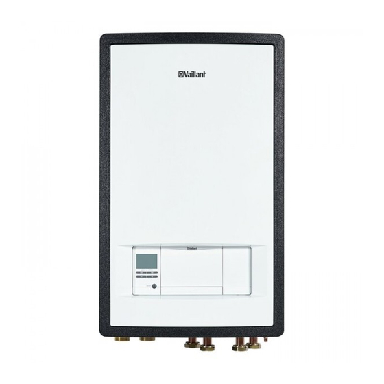
- Page 1 Operating instructions Hydraulic Station VWZ MEH 97/6 Publisher/manufacturer Vaillant GmbH Berghauser Str. 40 D-42859 Remscheid Tel. +492191 18 0 Fax +492191 18 2810 info@vaillant.de www.vaillant.de...
-
Page 2: Table Of Contents
Contents Contents Safety ..............3 Intended use ............3 General safety information ........3 Notes on the documentation ......5 Product description..........5 Heat pump system..........5 Design of the product..........5 Control elements............ 5 Control panel ............6 Description of the symbols ........6 Functional description of buttons...... -
Page 3: Safety
Safety 1 Safety General safety information 1.2.1 Danger caused by improper Intended use operation There is a risk of injury or death to the user or Improper operation may present a danger to others, or of damage to the product and other you and others, and cause material damage. - Page 4 ▶ If you cannot ensure the operation, have a competent person drain the heating installation. 1.2.5 Benchmark Vaillant is a licensed member of the Bench- mark Scheme which aims to improve the standards of installation and commissioning of domestic heating and hot water systems in the UK and to encourage regular servicing to optimise safety, efficiency and performance.
-
Page 5: Notes On The Documentation 2
Notes on the documentation 2 Notes on the documentation Design of the product ▶ Always observe all operating instructions that are en- closed with the installation components. ▶ Store these instructions and all other applicable docu- ments for further use. These instructions apply only to: Product VWZ MEH 97/6... -
Page 6: Control Panel
3 Product description Control panel Symbol Meaning Explanation – Without The dashed lines show the decoupling permitted range. module – Displayed statically: Filling – Filling pressure in the permitted pressure range in the – Displayed flashing: Filling building pressure outside of the circuit permitted range (meas-... -
Page 7: Type Designation And Serial Number
Operation 4 securing measure. After it is triggered, the safety cut-out Button Meaning must be replaced. Calling up the additional functions – Max. heating circuit temperature: 98 ℃ – Navigating between individual menu items – Increasing or decreasing the chosen set value Operation Adjustable values flash in the display. -
Page 8: Starting Up The Product
4 Operation Menu → Information → Cooling op. hours Starting up the product Menu → Information → Total operating hours 4.4.1 Opening the isolator devices You can use this function to display the operating hours Ask the competent person who installed the product to for heating mode, for domestic hot water mode, for cooling explain to you where these isolator devices are located mode and for overall operation. -
Page 9: Switching Off The Product's Functions
Care and maintenance 5 Switching off the product's functions Checking the system pressure 4.7.1 Switching off heating mode (Summer mode) Check the filling pressure of the heating installation every day for a week after initial start-up and mainten- Condition: No system control connected ance work, and then twice a year. -
Page 10: Decommissioning
Guarantee and customer service Guarantee Vaillant provides a full parts and labour guarantee for this appliance for the duration as shown on the enclosed re- gistration card which must be fully completed and returned within 30 days of installation. All appliances must be installed... -
Page 11: Appendix
Appendix Appendix Troubleshooting Problem Possible cause Remedy Building power supply switched off Switch on building power supply Domestic hot water or heating set to "off"/domestic Ensure that domestic hot water mode and/or hot water temperature or target temperature set too heating mode is activated in the system control. - Page 12 Appendix Setting level Values Unit Increment, select Factory setting Setting Min. Max. Building circuit water pressure Current value Building circuit flow rate Current value Compressor anti-cycling time Current value Immersion heater anti-cycling Current value time ℃ Target flow temp. Current value ℃...
- Page 16 0020291544_01 0020291544_01 30.01.2020 Supplier Vaillant Ltd. Nottingham Road Belper Derbyshire DE56 1JT Telephone 0330 100 3461 info@vaillant.co.uk www.vaillant.co.uk © These instructions, or parts thereof, are protected by copyright and may be reproduced or distributed only with the manufacturer's written consent. Subject to technical modifications.
- Page 17 Installation and maintenance instructions Hydraulic Station VWZ MEH 97/6 Publisher/manufacturer Vaillant GmbH Berghauser Str. 40 D-42859 Remscheid Tel. +492191 18 0 Fax +492191 18 2810 info@vaillant.de www.vaillant.de...
- Page 18 Contents Contents 6.16 Connecting the domestic hot water cylinder's temperature sensor..........32 6.17 Connecting the external prioritising diverter Safety ..............20 valve (optional) ............ 32 Action-related warnings ........20 6.18 Connecting the VR 70/VR 71 mixer module..32 Intended use ............20 6.19 Connecting cascades ..........
- Page 19 Contents 11.5 Using check programmes ........39 11.6 Checking the pre-charge pressure of the expansion vessel ..........39 11.7 Checking the high-pressure switch-off ....39 Draining .............. 39 12.1 Draining the product's heating circuit....39 12.2 Draining the heating installation ......40 Decommissioning..........
-
Page 20: Safety
1 Safety – compliance with all inspection and main- Safety tenance conditions listed in the instruc- Action-related warnings tions. Classification of action-related warnings Intended use also covers installation in ac- The action-related warnings are classified in cordance with the IP code. accordance with the severity of the possible Any other use that is not specified in these danger using the following warning signs and... -
Page 21: Regulations (Directives, Laws, Standards)
Safety 1 1.3.3 Risk of death due to lack of safety There is a risk of death if the connections are devices subject to leaks. ▶ Make sure that the product is positioned The basic diagrams included in this docu- ment do not show all safety devices required flush against the installation surface. -
Page 22: Notes On The Documentation
2 Notes on the documentation Notes on the documentation Safety devices 3.2.1 Frost protection function ▶ Always observe all the operating and installation instruc- tions included with the system components. The frost protection function for the system is controlled us- ▶... -
Page 23: Product Overview
Product description 3 Product overview 3.3.2 Design of the hydraulic block 3.3.1 Product design Manometer Domestic hot water Unit mounting bracket Electronics box with cylinder flow Expansion relief valve control PCB Prioritising diverter Expansion vessel Control for the indoor Building circuit return valve (heating cir- Hydraulic block unit... -
Page 24: Information On The Data Plate
Information Meaning Serial no. Unique unit identification number CE marking Nomen- Vaillant heat pump accessory clature Electro-hydraulic module 9 = 9 kW back-up heater 7 = integrated 3-port motorised The CE marking shows that the products comply with the... -
Page 25: Selecting The Installation Site
Set-up 4 Selecting the installation site ▶ The installation site must be below 2000 metres above sea level. ▶ Select a dry room that is frost-proof throughout and in which the maximum installation height is not exceeded and the environmental temperature is neither above nor below the permitted range. -
Page 26: Wall-Mounting The Product
5 Hydraulics installation – Removing the front casing Minimum clearance: 200 mm Wall-mounting the product Cut the enclosed adhesive strips for noise reduction into two equally sized pieces (3 cm x 3 cm). Affix the adhesive strips to the product as shown in the figure. -
Page 27: Connecting The Heat Pump To The Indoor Unit
Hydraulics installation 5 ▶ Connecting the building circuit For heating installations with solenoid valves or thermo- statically controlled valves, install a bypass with bypass valve in order to guarantee a volume flow of at least 40%. Connecting the heat pump to the indoor unit Connect the filling device with the enclosed seal to the product's heating return. -
Page 28: Electrical Installation
6 Electrical installation Electrical installation Electrical partition The electrical partitions are referred to as "disconnectors" Preparing the electrical installation in these instructions. The fuse or the circuit breaker that is installed in the building's meter/fuse box is usually used as Danger! the disconnector. -
Page 29: Establishing The Power Supply, 1~/230V
Electrical installation 6 – Establishing the power supply, 1~/230V Note that commercially available power supply cables do not usually have sufficient temperature ▶ Determine the type of connection: resistance. Case Connection type Connect the preinstalled power supply cable to the X300 connection with the heat pump electricity meter. -
Page 30: Opening The Power Supply Pcb's Electronics Box
6 Electrical installation 6.6.2 3~/400V dual power supply Establishing the power supply X311 X310 X300 Note the specifications on the sticker on the electronics box. Install two disconnectors for the product. Remove the front casing. (→ Page 26) Use the enclosed 5-pole power supply cable (5 x Open the power supply PCB's electronics box. -
Page 31: Installing The System Control In The Electronics Box
Electrical installation 6 Installing the system control in the electronics box 24V / eBUS Route 24 V cables and eBUS cables through the left- hand strain reliefs on the electronics box. 230V Route 230 V cables through the right-hand strain reliefs on the electronics box. -
Page 32: Opening The Control Pcb's Electronics Box
6 Electrical installation 6.12 Opening the control PCB's electronics box 6.15 Connecting the outdoor temperature sensor Condition: No system control connected ▶ Connect an outdoor temperature sensor to plug AF on terminal X41 on the control PCB. 6.16 Connecting the domestic hot water cylinder's temperature sensor Condition: No system control connected ▶... -
Page 33: Operation
Operation 7 Operation Checking and treating the heating water/filling and supplementary water Operating concept of the product Caution. The operating concept and the display and setting options of Risk of material damage due to poor-qual- the end user level are described in the operating instructions. ity heating water ▶... -
Page 34: Filling And Purging The Heating Installation
8 Start-up Caution. Risk of material damage if the heating water is treated with unsuitable additives. Unsuitable additives may cause changes in the components, noises in heating mode and possibly subsequent damage. ▶ Do not use any unsuitable antifreeze and corrosion inhibitors, biocides or sealants. -
Page 35: Purging
Start-up 8 Purging not run through completely, it restarts the next time the unit is switched on. Open the automatic air vent. 8.6.1 Ending the installation assistant Start the purge programme for the building circuit P06 using: Menu → Installer level → Test menu → Check ▶... -
Page 36: Setting The Anti-Legionella Function
8 Start-up Setting the anti-legionella function 8.14.2 Checking the domestic hot water generation ▶ ▶ Set the anti-legionella function using the system control. Check whether the cylinder is purged and the domestic hot water temperature is reached. To ensure sufficient anti-legionella protection, the electric back-up heater must be activated. -
Page 37: Starting Up The Optional System Control
Adapting the unit to the heating installation 9 ▶ 8.16 Starting up the optional system control Explain to the end user how the safety devices work and where they are located. The following work for starting up the system was carried ▶... -
Page 38: Resetting The Fault Memory
11 Inspection and maintenance 10.4 Resetting the fault memory 10.9.1 Replace the safety cut-out ▶ Press twice and then Delete and OK to delete the fault list. 10.5 Displaying Live Monitor (status codes) Status codes in the display provide information on the pro- duct's current operating mode. -
Page 39: Checking Maintenance Messages
Draining 12 11.2 Checking maintenance messages 11.6 Checking the pre-charge pressure of the expansion vessel If the symbol is shown in the display, the product requires maintenance work or the product is in comfort protection Close the service valves and drain the heating circuit. mode. -
Page 40: Draining The Heating Installation
Observe all relevant regulations. 14 Customer service Validity: Domestic To ensure regular servicing, it is strongly recommended that arrangements are made for a Maintenance Agreement. Please contact Vaillant Service Solutions for further details: Telephone: 0330 100 3461 Installation and maintenance instructions Hydraulic Station 0020291544_01... -
Page 41: Appendix
Appendix Appendix Functional diagram Automatic air vent Heating circuit, flow, domestic hot water Flow temperature sensor: Electric back-up heater Building circuit, flow, heating output Building circuit, return, heating Back-up heater Expansion relief valve, 3 bar Heating return to the outdoor unit Prioritising diverter valve Heating flow from the outdoor unit Diaphragm expansion vessel... -
Page 42: B Wiring Diagram
Appendix Wiring diagram X311 X310 X300 X312 X302 X314 X313 X328 X301 Power supply PCB [X328] Data connection to the control PCB For single power supply: 230 V bridge between [X313] Power supply for the control PCB or the op- X311 and X310;... -
Page 43: C Control Pcb
Appendix Control PCB 9 18 X100 / X106 eBUS 9 19 Control PCB [X16] Optional: Accessory (intermediate heat ex- changer pump) [X29] eBUS bus connection for the installed system [X15] Internal prioritising diverter valve for heating control circuit/cylinder charging [X51] Display edge connector [X11] Multi-function output 2: Domestic hot water [X35] Edge connector for optional external current circulation pump... -
Page 44: Basic Connection Diagram For The Energy Supply Company Lockout, Shutdown Via Connection S21
Appendix Basic connection diagram for the energy supply company lockout, shutdown via connection S21 L1 L2 L3 N L2 L3 N X211 X210 X200 X206 X311 X310 X300 X106 L1 L2 L3 L2 L3 N X211 X210 X200 X206 X311 X310 X300 X106... -
Page 45: Basic Connection Diagram For The Energy Supply Company Lockout, Shutdown Via Partition
Appendix Basic connection diagram for the energy supply company lockout, shutdown via partition L1 L2 L3 N L2 L3 N X211 X210 X200 X206 X311 X310 X300 X106 L1 L2 L3 L2 L3 N X211 X210 X200 X206 X311 X310 X300 X106 Meter/fuse box... -
Page 46: F Installer Level Overview
Appendix Installer level overview Setting level Values Unit Increment, select, ex- Factory setting Setting planation Min. Max. Installer level → Enter code 1 (competent person code 17) Installer level → Fault list → Current value F.XX – F.XX Installer level → Test menu → Statistics → Compressor hours Current value Compressor starts... - Page 47 Appendix Setting level Values Unit Increment, select, ex- Factory setting Setting planation Min. Max. T.0.42 Building circuit: Pressure T.0.43 Building circuit: Flow rate 4000 ℃ T.0.48 Air inlet temperature ℃ T.0.55 Compressor outlet tem- perature ℃ T.0.56 Compressor inlet temper- ature ℃...
- Page 48 Appendix Setting level Values Unit Increment, select, ex- Factory setting Setting planation Min. Max. ℃ DHW bivalence point ℃ Heating alt. point ℃ Max. flow temperature ℃ Min. flow temperature Heating mode activ. DHW activation K Cyl. charg. hysteresis Immers. heater mode Heating+DHW Heating Domestic hot water...
- Page 49 Appendix Setting level Values Unit Increment, select, ex- Factory setting Setting planation Min. Max. Compr. current limit 5–7 kW: 13–16 A 12 kW: 20–25 A Fan boost Compr. noise reduct. Only for products with cooling: None Active None, active cooling None cooling Cooling technology...
-
Page 50: G Status Codes
Appendix Status codes Statuscode Meaning Status external current anode Anode not connected, Anode OK, Anode Fault S.34 Heating mode: Frost pro- If the measured outdoor temperature falls below XX °C, the temperature of the heating circuit's flow tection and return is monitored. If the temperature difference exceeds the set value, the pump and com- pressor are started without a heat demand. - Page 51 Appendix Statuscode Meaning S.256 Fan unit 1: Air inlet The compressor does not start because the outdoor temperature at the fan is below the operating temp. too low limits. Heating mode: < -20 °C. Domestic hot water mode: < -20 °C. Cooling mode: < 15 °C. S.260 Fan unit 2: Fan blocked If the fan speed is 0 rpm, the heat pump is switched off for 15 minutes and then restarted.
-
Page 52: H Maintenance Messages
Appendix Statuscode Meaning S.314 Building circuit: Return Return temperature in the building circuit too high for the compressor to start. Heating: Return tem- temperature too high perature > 56 °C. Cooling: Return temperature > 35 °C. Cooling: Check that the 4-port diverter valve works correctly. -
Page 53: J Fault Codes
Appendix Fault codes Remedy Code Meaning Cause – – F.022 Water pressure too low Pressure loss in the building circuit Check the building circuit for leaks due to leakages or air pockets – Top up with water, purge – Building circuit pressure sensor –... - Page 54 Appendix Remedy Code Meaning Cause – – F.731 High-pressure switch open Refrigerant pressure too high. The Purging the building circuit integrated high-pressure switch – Too low a volume flow as a result in the outdoor unit has tripped at of closing single room controls in an 41.5 bar (g) or 42.5 bar (abs) underfloor heating system –...
- Page 55 Appendix Remedy Code Meaning Cause – – F.737 Condensation temperature too Temperature in the environment Reduce or stop the external heat high circuit (cooling mode) or building that is entering circuit (heating mode) too high for – Check the back-up heater (heats compressor operation up even though it is off in the –...
- Page 56 Appendix Remedy Code Meaning Cause – – F.785 Fan unit 2: Fan blocked There is no confirmation signal stat- Check the air route and, if required, ing that the fan is rotating remove any blockages – – F.788 Building circuit: Pump fault The electronics system of the high- Switch the heat pump off for at least efficiency pump has detected a...
-
Page 57: Kw Back-Up Heater At 230 V And At
Appendix Remedy Code Meaning Cause – – F.824 Building circuit 2: Pressure too Pressure loss in the building circuit Check the building circuit for leaks due to leakages or air pockets – Top up with water, purge – Note Building circuit pressure sensor –... -
Page 58: L Inspection And Maintenance Work
Appendix Inspection and maintenance work Maintenance work Interval Checking the pre-charge pressure of the expansion vessel Annually Check that the prioritising diverter valve can move easily (visually/audibly) Annually Checking the electronics boxes, removing dust from the ventilation slits Annually Characteristic values for the internal temperature sensors, hydraulic circuit Sensors: TT620 TT650 Temperature (°C) Resistance (ohms) -
Page 59: Characteristic Values For The Vrc Dcf Outdoor Temperature Sensor
Appendix Temperature (°C) Resistance (ohms) 3375 2700 2172 1758 1432 1173 Characteristic values for the VRC DCF outdoor temperature sensor Temperature (°C) Resistance (ohms) 2167 2067 1976 1862 1745 1619 1494 1387 1246 1128 1020 0020291544_01 Hydraulic Station Installation and maintenance instructions... -
Page 60: P Technical Data
Appendix Technical data Note The following performance data is only applicable to new products with clean heat exchangers. Technical data – General VWZ MEH 97/6 Product dimensions, width 440 mm Product dimensions, height 720 mm Product dimensions, depth 350 mm Weight, without packaging 20 kg Weight, ready for operation... - Page 61 Appendix VWZ MEH 97/6 ≤ 29 dB(A) Sound power A35/W7 in accord- ance with EN 12102 / EN 14511 L in cooling mode ≤ 30 dB(A) Sound power A35/W18 in accord- ance with EN 12102 / EN 14511 L in cooling mode Technical data –...
-
Page 62: Index
Index Index Low-water pressure protection ..........22 Maintenance message, checking ........39 Actuator test ................ 38 Maintenance work ............... 39 Actuators, checking ............. 38 Minimum clearances ............25 Basic diagram..............21 Operating concept ............7, 33 Building circuit connections ..........27 Parameters, resetting ............ - Page 64 0020291544_01 0020291544_01 30.01.2020 Supplier Vaillant Ltd. Nottingham Road Belper Derbyshire DE56 1JT Telephone 0330 100 3461 info@vaillant.co.uk www.vaillant.co.uk © These instructions, or parts thereof, are protected by copyright and may be reproduced or distributed only with the manufacturer's written consent. Subject to technical modifications.
Need help?
Do you have a question about the VIH QW 190/6 Series and is the answer not in the manual?
Questions and answers