Sign In
Upload
Download
Table of Contents
Contents
Add to my manuals
Delete from my manuals
Share
URL of this page:
HTML Link:
Bookmark this page
Add
Manual will be automatically added to "My Manuals"
Print this page
×
Bookmark added
×
Added to my manuals
Manuals
Brands
Doosan Manuals
Engine
V180TI
Operation & maintenance manual
Doosan V180TI Operation & Maintenance Manual
Hide thumbs
Also See for V180TI
:
Installation instructions manual
(91 pages)
1
2
3
4
5
6
7
8
9
10
11
12
13
14
15
16
17
18
19
20
21
22
23
24
25
26
27
28
29
30
31
32
33
34
35
36
37
38
39
40
41
42
43
44
45
46
47
48
49
50
51
52
53
54
55
56
57
58
59
60
61
62
63
64
65
66
67
68
69
70
71
72
73
74
75
76
77
78
79
80
81
82
83
84
85
86
87
88
89
90
91
92
93
94
95
96
97
98
99
100
101
102
103
104
105
106
107
108
109
110
111
112
113
114
115
116
117
118
119
120
121
122
123
124
125
126
127
128
129
130
131
132
133
134
135
136
137
138
139
140
141
142
143
144
145
146
147
148
149
150
151
152
153
154
155
156
157
158
159
160
161
162
163
164
165
166
167
168
169
170
171
172
173
174
175
176
177
178
179
180
181
182
183
184
185
186
187
188
189
190
191
192
193
194
195
196
197
198
199
200
201
202
203
204
205
206
207
208
209
210
211
212
213
214
215
216
217
218
219
220
221
222
223
224
225
226
227
228
229
230
231
232
233
234
235
236
237
238
239
240
241
242
243
244
245
246
247
248
249
250
251
252
253
254
255
256
257
258
259
260
261
262
263
264
265
266
267
268
269
270
271
272
273
274
275
276
277
278
279
280
281
282
283
284
285
286
287
288
289
290
291
292
293
294
Table Of Contents
295
page
of
295
Go
/
295
Contents
Table of Contents
Troubleshooting
Bookmarks
Table of Contents
Symbols Used in the Manual
Table of Contents
Engine Specification
Engine Sectional View
Engine Aspects
Engine Assembly Diagram
Engine Performance Curve
Engine Model & Serial Number
Safety Regulation
General Notes
Regulations Designed to Prevent Accidents with Injury to Persons
Regulations Designed to Prevent Damage to Engine and Premature Wear
Regulations Designed to Prevent Pollution
Engine Oil, Filter Element, Fuel Filter
Notes on Safety in Handling Used Engine Oil
3 Commissioning and Operation
Inspections before Operation
Cooling Water
Sea Water Pump
Intake & Exhaust Line
Fuel Line
Bottom of the Engine Room
Gauge Panel
Dutch Panel
Single Panel / Dual Panel
Dual Panel
Digital Gauge Panel Circuit Diagram
Digital Gauge Panel View
Engine Stop & Warning Devices
Starting
Engine Break-In
New Engine Break-In 20 Hours
Initial Two Hours of Break-In
Inspections after Starting
Operating after Break-In 20 Hours
Pressure of Lubricating Oil
Temperature of Cooling Water
Check after Initial 50 Hours Operation
Operation in Winter
Prevention against the Freeze of Cooling Water
Prevention against Excessive Cooling
Tuning the Engine
General Repair Instructions
4 General Information
Periodical Inspection & Maintenance
Cooling System
Coolant Level Check and Refill
Contamination Check of Coolant and Quantity of Anti-Freeze
Anti-Freeze
Heat Exchanger and Cooling Line Cleaning
Fresh Water Line Cleaning
Check and Adjust of V-Belt Tension
Thermostat
Replacing Thermostat and Precautions for Handling
Lubrication System
Oil Level
How to Re-Mark the Oil Dipstick
Exchanging of Lubrication Oil
Oil Drainage
Recommend of Lubricating Oil
Replacement of Oil Filter Cartridge
Engine Oil Viscosity - Ambient Temperature
Oil Centrifugal Filter
Marine Gear Oil Change
Cylinder Compression Pressure
Intake & Exhaust System
Cleaning & Change of the Air Filter Element
Inter-Cooler
Turbo-Charger Cleaning
Fuel System
Priming Pump Strainer Cleaning
Fuel Tank Cleaning & Checking
How to Select Fuel Oil
Fuel Oil Selection Chart
Water Separator
Fuel Filter Exchanging
Checking the Fuel Injection Timing
Injection Nozzle Maintenance
Bleeding of the Fuel System
Electric System
Warning Lamp Check
Valve Clearance
When the Engine Is Not Used Long Time
When the Engine Is Sunk
5 Main Accessory Parts
Reduction Gear
Front Power Take off
PTO Description and Operation
How to Use PTO
Checking Engagement Load
PTO Adjustment
Adjusting Rings
Facing Check (PTO)
Lubrication Point
Exploded View of Typical 11-1/2″ ~ 14″ Twin Clutch
Front Power Take-Off (F.P.T.O)
Propeller Selection
Alternator
Electric System
Starter Motor
6 Disassembly and Assembly of Major Components
Cylinder Block Inspection
Cylinder Head Inspection
Cylinder Liner Measurement
Cylinder Head Disassembly
Distortion of Cylinder Head Bottom Face
Check of Valve Guide
Valve Seat
Valve Spring Check
Squareness of Valve Spring
Assembling Cylinder Head
Rocker Arm Inspection
Camshaft Inspection
Crankshaft Inspection
Inspection on Crankshaft Bearing
Run out of Crankshaft
How to Utilize Plastic Gauge
How to Utilize the Cylinder Gauge
Piston Disassembling
Piston Inspection
Piston Ring & Ring Groove Inspection
Piston Pin Inspection
Connecting Rod Inspection
Piston Reassembling
Injection Nozzle Inspection
Engine Re-Assembly
Flywheel Housing
Tacho Sensor
Flywheel
Oil Cooler
Heat Exchanger
Piston
Starting Motor
Connecting Rod Bolt Tightening Order
Front Oil Seal Holder
Oil Pan
Oil Pump
Vibration Damper
Cylinder Head
Nozzle
Rocker Arm
Valve Clearance Adjust Procedure
Cylinder Head Cover
Fuel Injection Pump
Injection Timing
Flywheel Housing Cover
Fresh Water Pump
Intake Manifold
Exhaust Manifold
Turbocharger
Fuel Filter
Fuel Injection Pipe
Idle Pulley
Trial Test after Maintenance
7 Main Parts Maintenance
Lubricating System Maintenance
Oil Pump Maintenance
Cooling System Maintenance
Fresh Water Pump Assembly
Fuel System Maintenance
Injection Pump Maintenance
Rack Diagram
Boost Compensator Pressure
Fuel Feed Pump
Fuel Feed Pump Disassembly and Inspection
Fuel Feed Pump Testing
Injection Nozzle
Turbo-Charger Specification
Construction of the Turbo-Charger
Inspection of the Turbo-Charger
Turbo Charge Identification
Turbocharger Disassembly
Turbocharger Cleaning
Assembly Turbine Wheel
Turbine Housing
Compressor Housing
Bearing Housing
Compressor Wheel
Oil Slinger
Turbocharger Assembly
Checking of the Rotor for Rotating Condition
Checking of the Rotor End Play
Precautions for Reassembling the Turbocharger Onto the Engine
Troubleshooting
Hard to Start the Engine
Insufficient Output
Overheating
Black Smoke Is Produced
White Smoke Is Produced
Starter Motor will Not Turn or Output Less Power
Hydraulic System will Not Operate or to Slow Function
Battery Is Dead or Not Chargeable
Standard Table of Tightening Torque
Standard Bolt Tightening Torque Table
Tightening Torque for Plug Screw
Governor Actuator
Outside View and Main Components of Governor
Control Unit
Specifications
Description of Controller Terminology
Controller Wiring
How to Adjust the Engine Performance (for New Controllers)
Adjusting the Starting Fuel
Setting the Idle Rpm
Droop Operation
Auxiliary Input
Auxiliary Supply
Remote Speed Adjustment
8 Troubleshooting
Control Unit Components
Description of Control Mode Items
Installing (Mounting) the Controller and Cautions
Adjustment (Tuning) Order and Method
External Wiring Connections
Adjusting the Speed Externally
Mounting and Connecting the Magnetic Speed Sensor
Accessory Input (Automatic Parallel)
Controller Lamp Display (Diagnosis) Functions
Droop Parallel Operating Mode (Manual Parallel)
Digital Speed Controller
Product Appearance
Product Specification
Product I/O Signals
Product System Diagram
Product Dimension
Connecting to the Engine
Installation
Operating Sequence for the Controller
Connecting to Speed Trim, Droop, Idle and Other Inputs
Connecting to Crank, Run, over Speed and Communication
Configuration and Operation
Input Keys
LCD Display Menu
LCD Displays after Powered on
LCD Main Menu Display
Engine Type Setup Menu
Date/Time Setup Menu
PID Auto Setup Menu
PID Gain Setup Menu
Alarm List Menu
Default Setup Menu
System Info Menu
Designated Parameters by Engine Type
Engine Configuration
Configuring Set Idle Rpm
Configuring Set over Speed
Configuring Cranking Rpm
Configuring Gear Number
Configuring Speed Ramping
Configuring Starting Fuel
Configuring Low Battery
Configuring Max Current
Configuring Droop Gain
Droop Function
PID Gain Setup Configuration
Configuring PID Sampling Time
PID Auto Setup Value Configuration
Date/Time Value Configuration
Alarm Code Table
Alarm List
Default Setup Functions
System Info Functions
LCD Setup Functions
System Monitor Functions
Operating Sequence for Digital Speed Controller
Controller Troubleshooting
Digital Panel for Marine Engines
Digital Panel Components and Optional Accessories
General Information
Product Information
Digital Panel Specifications
Product Specification
Cautions
Digital Panel Installation
Product Installation
Installing Stationary Type Digital Panel
Installing Mounting Type Digital Panel
Back Side
Digital Panel Part Names, Operation and Settings
Front Side
External Connection Terminals
Power Connector
Signal Connector
CAN Communication Connector
CCTV Connector
External Buzzer Connector
Fuse and Internal Buzzer (Digital Panel)
Key Switch (Digital Panel)
USB Connector
Start/Stop Button (Digital Panel)
Function Keys (Digital Panel)
Detailed Settings (Digital Panel)
Battery Voltage
Check Sensor Light
Display Structure (Digital Panel)
Engine Oil Pressure
Engine Speed (Tachometer)
Exhaust Gas Temperature
Gearbox Oil Pressure
Engine Oil Pressure
Engine Water Temperature
Exhaust Gas Temperature
Battery Voltage
Check Sensor Light
Gearbox Oil Pressure
Engine Alarm
Engine Stop
Spare Sensor
Event Summary
System Booting and Functional Check (Digital Panel)
Multi Panel Structure
How to Install Multi Panels
Multi Panel Settings
Digital Panel Manager
PC Communication Connection
Software Installation and Execution
Display Structure and Detailed Functions (Digital Panel)
Menu Structure
Operation Record Files (Digital Panel)
Setting Functions by Permission Level
Default Settings (Digital Panel)
Event Settings (Digital Panel)
Sensor Value Mapping Tab (Digital Panel)
Maintenance (Digital Panel)
Troubleshooting (Digital Panel)
A/S Service Information
Warranty
Warranty and A/S Service
Advertisement
Quick Links
1
Engine Specification
Download this manual
Operation &
Maintenance Manual
MARINE ENGINE
V158TI, V180TI, V222TI,
AD158TI, AD180TI, AD222TI
950106-038007EN
Table of
Contents
Previous
Page
Next
Page
1
2
3
4
5
Advertisement
Table of Contents
Troubleshooting
Troubleshooting
173
Troubleshooting
201
Controller Troubleshooting
251
Maintenance (Digital Panel)
291
Need help?
Do you have a question about the V180TI and is the answer not in the manual?
Ask a question
Questions and answers
Related Manuals for Doosan V180TI
Engine Doosan MD Series Installation Instructions Manual
Md, l, v series marine diesel engine (91 pages)
Engine Doosan V Series Installation Instructions Manual
Md, l, v series marine diesel engine (91 pages)
Engine Doosan V158TI Operation & Maintenance Manual
(295 pages)
Engine Doosan V222TI Operation & Maintenance Manual
(295 pages)
Engine Doosan DV11 Operation And Maintenance Manual
(221 pages)
Engine Doosan G424FE Service Manual
Lp and lp/dual fuel engines (306 pages)
Engine Doosan G420F Service Manual
Lp/gasoline and lp/dual fuel engines (326 pages)
Engine Doosan G430 LP Service Manual
G430 lp engine (182 pages)
Engine Doosan DB33A Service Manual
Diesel engine 3.3 liter (79 pages)
Engine Doosan D35S-5 Service Manual
(152 pages)
Engine Doosan DP158LCF Operation & Maintenance Manual
Generator diesel engine (160 pages)
Engine Doosan DE12T Operation & Maintenance Manual
(176 pages)
Engine Doosan D35S-5 Service Manual
(366 pages)
Engine Doosan DL06 Operation Manual
Interim tier iv (211 pages)
Engine Doosan DL06 Manual
(207 pages)
Engine Doosan A2300 Service Manual
(242 pages)
Summarization of Contents
1. SPECIFICATION
1.1 Engine Specification
Detailed specifications for various engine models, including performance and dimensions.
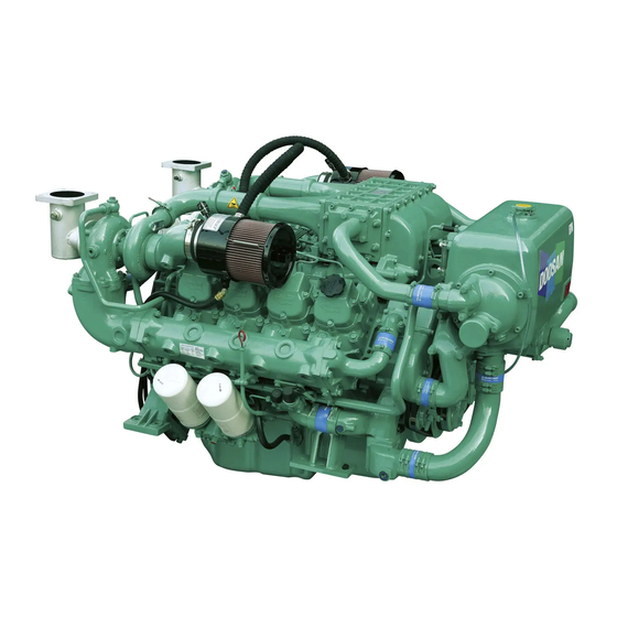
1.2 Engine Aspects
Explains engine components and provides sectional views for better understanding.
1.3 Engine Performance Curve
Graphical representation of engine output and fuel consumption across different operating conditions.
1.4 Engine Model & Serial Number
Information on identifying engine model and serial number for service and parts.
2. SAFETY REGULATIONS
2.1 General Notes
General safety guidelines for operating and maintaining engines, emphasizing training and awareness.
2.2 Regulations Designed to Prevent Accidents with Injury to Persons
Safety rules for commissioning, starting, operation, maintenance, and repair work to prevent injuries.
2.3 Regulations Designed to Prevent Damage to Engine and Premature Wear
Guidelines to prevent engine damage and premature wear by proper usage and maintenance.
3. COMMISSIONING AND OPERATION
3.1 Inspections before Operation
Checks for lubricating oil, cooling water, sea water pump, and fuel lines before engine operation.
3.2 Starting
Procedures for starting the engine using both analog and digital gauge panels.
3.3 Engine Break-in
Instructions for the initial 20 hours of operation to ensure maximum engine performance and life.
3.4 Inspections after Starting
Checks after engine start, including oil pressure, warning lamps, and exhaust gas conditions.
3.7 Tuning the Engine
Procedures for engine tune-up to restore lost power and performance due to wear or deterioration.
4. GENERAL INFORMATION
4.1 General Repair Instructions
Essential guidelines for performing service operations, including safety, tool usage, and part handling.
4.2 Periodical Inspection & Maintenance
Schedule and details for regular inspections and maintenance to ensure trouble-free engine performance.
4.3 Cooling System
Maintenance procedures for the cooling system, including coolant checks, changes, and heat exchanger cleaning.
4.4 Lubrication System
Maintenance procedures for the lubrication system, including oil level checks and oil changes.
4.5 Intake & Exhaust System
Maintenance for intake and exhaust systems, including air filter cleaning and turbocharger inspection.
4.6 Fuel System
Maintenance for the fuel system, including fuel tank, water separator, and injection timing.
4.8 Valve Clearance
Procedures for adjusting valve clearance, especially after initial operation or overhaul.
5. MAIN ACCESSORY PARTS
5.1 Reduction Gear
Construction, operation, and maintenance of the reduction gear used for high-speed engines.
5.2 Front Power Take Off
Description, operation, and usage instructions for the front power take-off (PTO) system.
5.3 Propeller Selection
Guidance on selecting the correct propeller for optimal engine performance and economy.
6. DISASSEMBLY AND ASSEMBLY OF MAJOR COMPONENTS
6.1 Disassembly
Step-by-step instructions for disassembling major engine components like cooling water system and oil components.
6.2 Inspection
Procedures for inspecting critical engine parts such as cylinder block, liner, head, and crankshaft for wear or damage.
6.3 Engine Re-assembly
Detailed steps for reassembling the engine components after inspection and repair.
6.4 Trial Test after Maintenance
Procedures for performing a trial test after maintenance to ensure proper operation and prevent damage.
7. MAIN PARTS MAINTENANCE
7.1 Lubricating System
Maintenance procedures for the lubricating system, including specifications and oil pump details.
7.3 Fuel System
Maintenance of the fuel system, including injection pump calibration and nozzle maintenance.
7.4 Turbo-charger
Specifications, construction, inspection, and assembly procedures for the turbocharger.
8. TROUBLE SHOOTING
Hard to start the engine
Identifies common causes and remedies for engine starting difficulties.
Insufficient output
Diagnoses and suggests solutions for reduced engine power or performance issues.
Overheating
Explains causes and solutions for engine overheating problems.
Black smoke is produced.
Troubleshooting guide for black smoke from the engine exhaust.
White smoke is produced.
Troubleshooting guide for white smoke from the engine exhaust.
Appendix
Standard table of tightening torque
Reference table for standard tightening torque values for various engine components and bolts.
Piston
Specifications and allowable limits for piston dimensions and wear.
Connecting rod
Specifications and allowable limits for connecting rod dimensions and wear.
Oil pressure
Normal and no-load oil pressure specifications and allowable limits.
Governor Actuator Controller
Definition
Explains the function of the governor actuator in controlling engine speed and fuel flow.
Appearance and Installation
Provides an overview of the governor actuator's appearance and installation on the engine.
Operating Principles
Describes how the governor system works to maintain engine speed and output.
Product Specifications
Details general and mechanical specifications for the governor controller product.
Control Unit (1)
Explains the functions and features of the electronic control unit for engine speed.
Specifications
Lists performance, terminal sensitivity, input power, and environmental specifications for the controller.
Part Names, Operation and Settings
Details the components, operation, and settings of the digital panel system.
External Connection Terminals
Details the pin assignments and functions for external connections like power, signal, and CAN.
Function Keys
Details the functions of the various keys used for navigating menus and adjusting settings.
Detailed Settings
Describes how to configure engine models, master/slave settings, and other operational parameters.
Display Structure and Detailed Functions
Explains the controller's display structure, menus, and detailed functions.
Maintenance
General guidelines for maintaining the digital speed controller and its components.
Troubleshooting
Provides possible measures for users to resolve problems encountered while using the device.
Warranty and A/S Service
Information regarding product warranty and customer service procedures.
Appendix
Lists compatible engine models with their specifications for reference.
Table of Contents
Save PDF
Print
Rename the bookmark
Delete bookmark?
Delete from my manuals?
Login
Sign In
OR
Sign in with Facebook
Sign in with Google
Upload manual
Upload from disk
Upload from URL
Need help?
Do you have a question about the V180TI and is the answer not in the manual?
Questions and answers