
Related Manuals for Olympus IV9435GL


Summarization of Contents
Introduction
Intended use
Purpose of the instrument for inspection and observation of machinery interiors.
Instruction manual
Contains operations and safe handling methods for the instrument.
Product configuration
Details devices required and compatible with the instrument.
Expanded functionality of the IPLEX G Lite series
Explains how to use the stereo measurement function with optional accessories.
Safety precautions
General safety precautions
Strict compliance with handling precautions for safe operation and to prevent damage.
Battery precautions
Precautions for handling batteries to prevent leakage, heat, or electric shock.
Rating plate/caution plate
Conformity label
Displays safety ratings, serial numbers, and compliance marks for the product.
Rating, model, serial number, precautions
Provides information on product identification and safety warnings.
1 Unpacking
1-1 Unpacking
Checklist to ensure all items are included after receiving the instrument.
Storing the optical adapter case
Instructions on how to store optical adapters and related accessories in the case.
2 Options
Stereo optical adapter
Lists items included with the stereo optical adapter, such as the adapter and data media.
Optical adapter
Lists items included with the optical adapter, such as the adapter and O-rings.
2 Nomenclature
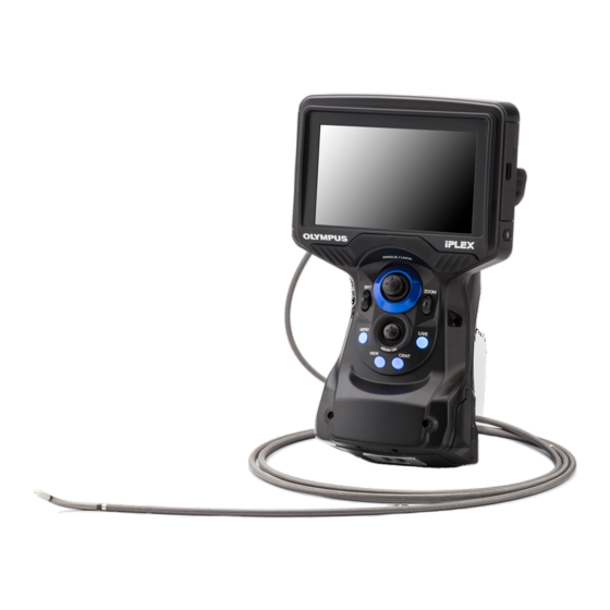
2-1 Nomenclature
Identifies and labels the various parts and buttons of the main unit.
2-2 Distal end/optical adapter nomenclature
Identifies parts of the distal end and optical adapters for 4-mm and 6-mm insertion tubes.
2-3 LCD monitor nomenclature
Identifies icons, indicators, and elements displayed on the live and freeze screens.
4 Basic operation
4-1 Turning ON the power
Procedures for powering the instrument on and off, and system startup time.
Selecting an optical adapter
How to select the correct optical adapter from the list displayed upon powering on.
4-2 Checking the remaining battery level
Displays the battery status indicator and its meaning for power levels.
4-3 Turning ON the light
How to check and adjust the illumination at the distal end of the insertion tube.
4-4 Operating the instrument
Overview of controls like buttons, levers, and joysticks on the main unit and touch panel.
4-5 Observing the inspection object
Guides for inserting the tube, operating angulation, locking angles, and removing the tube.
4-6 Adjusting the image display
Instructions for freezing images and using the zoom function for enlarged views.
4-7 Switching the folder on the live screen
How to change the folder for recording or playback operations on the live screen.
4-8 Recording images
Preparation for recording images, including formatting media and display information.
4-9 Playing back the image
How to display recorded images in full-screen or thumbnail views.
4-10 Using the constant video
Information on the feature that automatically records movies while the live screen is displayed.
4-11 Displaying live images on the external monitor
Connecting an external monitor via HDMI cable to display live images.
4-12 Displaying live images on the mobile terminal
Connecting a mobile terminal via wireless LAN for live image display.
4-13 Using recorded images on a PC
Instructions on how to transfer and use recorded images on a computer with specific software.
5 Menu operations and functions
5-1 Menu operations
How to navigate and operate the instrument's menus using buttons, joysticks, or the touch panel.
5-2 Using the live screen/freeze screen
Settings and functions available on the live and freeze screens, such as title input and white balance.
5-3 Using the thumbnail/view screens
Operations for managing recorded files and folders, including delete, move, and rename.
6 Measurement functions
6-1 Scaler measurement function
How to use the scaler measurement to determine object lengths based on a preset reference length.
6-2 Stereo measurement function
Details on performing stereo measurements using a stereo optical adapter for 3D coordinate calculations.
7 Observation of special light
7-1 Replacing the LED unit
Instructions for removing and attaching different types of LED units for special light observation.
7-2 Observation using UV light
Guidance on using the UV LED unit, including white balance reset and checking illumination.
7-3 Observation using IR light
Guidance on using the IR LED unit, including checking illumination and managing white streaks.
8 Troubleshooting
8-1 Troubleshooting guide
Common error messages and their recommended solutions for instrument issues.
Common problems
Lists common issues encountered with the instrument and their corresponding causes and solutions.
Requesting repair of this product
Guidelines and procedures for contacting Olympus for instrument repair services.
9 Storage and maintenance
9-1 Replacing the battery
Recommendations and contact information for battery replacement when performance degrades.
9-2 Replacing the O-ring
Instructions for replacing O-rings, noting differences between adapter types.
9-3 Cleaning components
Detailed instructions for cleaning various parts of the instrument, including the insertion tube.
9-4 Storage precautions
Guidelines for storing the product under normal room temperature and humidity.
10 Specifications
10-1 Operating environment
Specifies the environmental conditions such as temperature, humidity, and altitude for instrument operation.
10-2 Other specifications
Details on optical system, distal end dimensions, angulation, and flexible section properties.
10-3 Optical adapter specifications
Technical specifications for various 4-mm type optical adapters.
For 6-mm type insertion tube
Technical specifications for various 6-mm type optical adapters.
Appendix
System chart
A visual diagram showing the connections and relationships between the main unit and accessories.
Need help?
Do you have a question about the IV9435GL and is the answer not in the manual?
Questions and answers