
Related Manuals for Woodward SPM-D2-10B/PSY5


Summarization of Contents
Chapter 2. General Information
Intended Use
Specifies the allowed operational uses for the unit and prerequisites for safe operation.
Chapter 4. Installation
Wiring Diagrams
Illustrates electrical connections for the SPM-D2-10B/PSY5-FU-D unit.
Reference Point and Power Supply
Details reference point terminal and power supply connections for various unit types.
Measuring Inputs System 2
Describes voltage measurement connections for System 2.
System 1 Voltage Measurement
Details voltage measurement connections for System 1.
Discrete Inputs
Explains discrete input terminals, their functions, and connection details.
Relay and Controller Outputs
Details relay outputs for CB control/messages and unit's voltage/frequency controllers.
Chapter 5. Description of Functions
Functionality and Conditions
Explains unit functionality via input signals, conditions, and function tables.
Control Inputs and Isolation
Describes discrete control inputs and power supply isolation methods.
Operating Modes
Details operation modes: no-load, synchronization, synch check, isolated operation, and black start.
Status Indicators and Control Outputs
Explains 'Closed' LED flashes and control output functions.
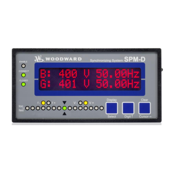
Chapter 6. Display and Operating Elements
Front Panel Overview
Overview of the front foil, LC-display, and touch-sensitive elements.
LEDs and Push Buttons Explanation
Brief explanation of unit LEDs and push buttons.
Detailed LED Descriptions
Detailed descriptions of LED indications and their functions.
Push Button Functions
Explains the functions of the Display/Select and Digit/Cursor push buttons.
LC Display Modes
Describes LC display modes for monitoring voltage, frequency, and alarms.
Chapter 7. Configuration
Toolkit Installation and Usage
Instructions for installing and using the Toolkit software for device configuration.
Basic Data and Settings Configuration
Details basic data, password protection, factory defaults, general settings, and no-load control.
Controller Configuration
Explains parameters for frequency and voltage controllers, including gain and insensitivity.
Synchronization and Black Start Configuration
Covers synchronization parameters, phase angle control, time monitoring, and black start setup.
Output and Password Configuration
Details relay output settings and password code configuration.
Chapter 8. Commissioning
Safety Precautions and Procedure
Highlights safety precautions and provides a step-by-step commissioning guide.
Synchronizing and Black Start Commissioning
Details steps for synchronizing the breaker and commissioning black start.
Appendix C. Technical Data
Technical Specifications Overview
Details electrical, environmental, housing, and communication specifications.
Appendix D. Service Options
Service, Repair, and Contact Information
Outlines service options, repair procedures, contact details, and engineering services.
Need help?
Do you have a question about the SPM-D2-10B/PSY5 and is the answer not in the manual?
Questions and answers