Table of Contents
Advertisement
Quick Links
Manual
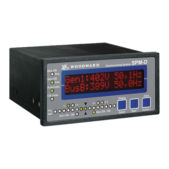
SPM-D10B/PSY4
- Synchronizing System -
Version 1.1xx
© All Rights reserved. Subject to technical modifications.
Version 37184C
2008/09/Stuttgart
Woodward GmbH
Handwerkstr. 29
70565 Stuttgart - Germany
Tel: +49 (0) 711 78954-0
Fax: +49 (0) 711 78954-100
E-mail: stgt-info@woodward.com
Website: woodward.com/power
Advertisement
Table of Contents

Related Manuals for Woodward SPM-D10B/PSY4


Summary of Contents for Woodward SPM-D10B/PSY4
- Page 1 Manual SPM-D10B/PSY4 - Synchronizing System - Version 1.1xx © All Rights reserved. Subject to technical modifications. Version 37184C 2008/09/Stuttgart Woodward GmbH Handwerkstr. 29 70565 Stuttgart - Germany Tel: +49 (0) 711 78954-0 Fax: +49 (0) 711 78954-100 E-mail: stgt-info@woodward.com Website: woodward.com/power...
-
Page 2: Table Of Contents
4.3 Controller configuration ..............................17 4.3.1 No-load control ............................... 17 4.3.2 Frequency controller............................... 18 4.3.3 Voltage controller (SPM-D10B/PSY4-FU-D only) ....................19 4.3.4 Synchronization functions ............................20 4.3.5 Black start ................................21 4.3.6 Synchronization time monitoring ..........................21 ... -
Page 3: Introduction
The unit must only be operated for the uses described in these manual. The prere- quisite for a proper and safe operation of the product is correct transportation, sto- rage, and installation as well as careful operation and maintenance. SPM-D10B/PSY4 Manual © Woodward Page 3/28... -
Page 4: Measurement Data
1.2.2 Voltage measuring inputs NOTE The SPM-D10B/PSY4 can operate (monitor) only one synchronization point. The voltage at terminals 23/24 (system 1) is the voltage to which the assessment of the synchronization at terminals 20/21 (system 2) refers. The synchronization voltage can be, e. g., the mains or busbar voltage. -
Page 5: Auxiliary And Control Inputs
Reply: CB is open Terminal Accompanying Name Zero terminals (according to DIN 40 719 Part 3, 5.8.3) NO contact Enable CB 2.5 mm² Enable isolated operation 2.5 mm² NC contact Reply: CB is open 2.5 mm² SPM-D10B/PSY4 Manual © Woodward Page 5/28 37184C... -
Page 6: Auxiliary And Control Outputs
Note: The relays close when the function is fulfilled. Readiness for operation 2.5 mm² c.) Controller outputs The controllers are configured as three-point controllers (made of a change-over con- tact and a normally open contact). • SPM-D10B/PSY4-F-D Speed/frequency max. 250 V AC Speed Lower governor... -
Page 7: Description Of Functions
- Parameter "Automatic no load control ON" - valid for f control: Voltage system 2 > 50 % rated voltage V - SPM-D10B/PSY4-FU-D only - valid for V control: Frequency system 2 > 90 % of rated frequency f Isolated operation - Voltage system 2 >... -
Page 8: Control Inputs
• Reference points connected with 0 V: Bridge between terminal 7 and terminal 2 (0 V) • Reference point of the discrete inputs potential-free: Terminal 2: 0 V (Power supply) Terminal 7: 0 V or N (control voltage) SPM-D10B/PSY4 Manual © Woodward Page 8/28 37184C... -
Page 9: Operating States
2.6 Operating states 2.6.1 No load operation The frequency and the voltage (SPM-D10B/PSY4-FU-D only) of system 2 are con- trolled to the configured setpoint value by operating accordingly the relays of the three-position controller for speed and voltage (SPM-D10B/PSY4-FU-D only; see al- so chapter 2.1 "Function table"... -
Page 10: Display Elements And Controls
"Select" ..................Confirm selection "Digit“ ....................Increase digit "Clear" ..................Acknowledge alarms "Cursor" ................Input cursor 1 to the right _____________________________________________________________ Display "Synchronism" ............Synchronism system 1 and 2 "LC display" ..................... LC display SPM-D10B/PSY4 Manual © Woodward Page 10/28 37184C... -
Page 11: Light-Emitting Diodes
The LED “Closed” signals the reply of the circuit breaker. The LED is illuminated if the discrete input “Reply: CB is open” is not set and it expires if the discrete input is set (see also chapter 2.2 “LED "Closed" flashes” on page 7). SPM-D10B/PSY4 Manual © Woodward Page 11/28... -
Page 12: Buttons
Configuration .... "Cursor→" This button is used to move the cursor one posi- tion to the right. When the last right-hand position is reached, the cursor automatically moves to the first posi- tion left-hand of the value to be entered. SPM-D10B/PSY4 Manual © Woodward Page 12/28 37184C... -
Page 13: Display
2. Right hand to the % sign a blinking arrow shows the activity of the voltage controller (SPM-D10B/PSY4-FU-D only), right hand to the unit "Hz" the activity of the frequency controller is displayed. If the point of the arrow shows to the top the controller outputs "higher"... -
Page 14: Configuration Screens (Input Of The Parameters)
10 minutes, the unit automatically returns to the automatic mode. Language selection German/English SPRACHE/LANGUAGE english Selection of the language. Software version Software version x.xxxx Display of the software version. SPM-D10B/PSY4 Manual © Woodward Page 14/28 37184C... -
Page 15: Password Protection
(Code level 0/1/2). If an incorrect code number has been entered, confi- guration is blocked. OFF ..Access to configuration screens is permanently set to code level 2 and the code number is not queried. SPM-D10B/PSY4 Manual © Woodward Page 15/28 37184C... -
Page 16: Basic Settings
This value is used to define the permitted limits for synchronization. Setpoint voltage system 2 50..440 V Voltage System 2 setpoint 000V This value of the voltage specifies the setpoint of the voltage of system 2 for no-load and isolated operation. SPM-D10B/PSY4-FU-D only SPM-D10B/PSY4 Manual © Woodward Page 16/28 37184C... -
Page 17: Controller Configuration
(see also chapter 2.1 “Function table” on page 7): • CB release is present: Frequency and if applicable voltage are controlled. • Release CB is not present: No control is carried out. SPM-D10B/PSY4 Manual © Woodward Page 17/28 37184C... -
Page 18: Frequency Controller
Gain Kp = 00.00 The gain factor K influences the operating time of the relays. By increasing the fac- tor, the operating time can be increased in the event of a certain control deviation. SPM-D10B/PSY4 Manual © Woodward Page 18/28 37184C... -
Page 19: Voltage Controller (Spm-D10B/Psy4-Fu-D Only)
4.3.3 Voltage controller (SPM-D10B/PSY4-FU-D only) Voltage controller ON/OFF Volt. controller ON .... Generator voltage control is carried out. The generator voltage is con- trolled in various manners depending on the task (no load / isolated op- eration / synchronization). The subsequent screens of this option are displayed. -
Page 20: Synchronization Functions
Closing time =000ms The inherent switching time of the circuit breaker corresponds to the lead time of the connect command. The connect command will be issued at the entered time before the synchronization point. SPM-D10B/PSY4 Manual © Woodward Page 20/28 37184C... -
Page 21: Black Start
This screen mask only appears in code level 2. Here the code number is defined which must be set on the item to get into code level 2 (commissioner). More informa- tion about password protection see on page 15. SPM-D10B/PSY4 Manual © Woodward Page 21/28... -
Page 22: Commissioning
The absence of a measuring voltage can lead to an asyn- chronous switching command when the black start is active. 7. Checking the signal "Enable CB": After applying the "Enable CB" the LED "Enable” on the pressure-sensitive front membrane lights up. SPM-D10B/PSY4 Manual © Woodward Page 22/28 37184C... - Page 23 Before inserting the circuit breaker it is absolutely necessary to check whether the measuring voltages are attached correctly. It must also be checked whether the syn- chronous conditions are fulfilled in the moment when the SPM-D10B/PSY4 issues an add-on pulse. This check can easily occur in measuring the difference voltage direct- ly at the appropriate circuit breaker.
-
Page 24: Appendix
- Weight ............depending on model, approx. 800 g Protection - Degree of protection ............. IP21; from front IP42 - Pressure-sensitive front membrane ..........isolating surface - Disturbance test (EC) ....Tested according to valid EN codes of practice SPM-D10B/PSY4 Manual © Woodward Page 24/28 37184C... -
Page 25: Dimensions
Degree of protection IP 21, front IP 42 Weight depending on model, approx. 800 g Front view Back plate mounting optionally Bottom view Back view with connecting terminals 2003-03-18 | SPM-D10B/PSY4 Dimensions 1203-ab.skf SPM-D10B/PSY4 Manual © Woodward Page 25/28 37184C... -
Page 26: Wiring Diagram
6.3 Wiring diagram 6.3.1 SPM-D10B/PSY4-F-D lower SPEED Three-position controller raise Voltage - System 2 - L2 alternatively Voltage - System 2 - L1 Common Enable isolated operation Reply: CB is open Enable CB Command: close CB Voltage - System 1 - L2... -
Page 27: Spm-D10B/Psy4-Fu-D
6.3.2 SPM-D10B/PSY4-FU-D lower SPEED Three-position controller raise lower VOLTAGE Three-position controller raise Voltage - System 2 - L2 alternatively Voltage - System 2 - L1 Common Enable isolated operation Reply: CB is open Enable CB Command: close CB Voltage - System 1 - L2... -
Page 28: Parameter List
7 Parameter list SPM-D10B/PSY4 Synchronizing system P arameter list Version ____________________________________________________ Project ____________________________________________________ Device number ________________________________ Date _________ Option Parameter Setting range Default Customer settings Line 1 - Text - Line 2 setting Sprache/Language German/English English Software version 1.1xxx Enter Code number 0..9999...
Need help?
Do you have a question about the SPM-D10B/PSY4 and is the answer not in the manual?
Questions and answers