Woodward UG40 Installation And Commissioning Manual
Governor with digital interface
Hide thumbs
Also See for UG40:
- Installation and operation manual (28 pages) ,
- Installation and operation manual (63 pages) ,
- Installation and operation manual (28 pages)

Subscribe to Our Youtube Channel
Related Manuals for Woodward UG40


Summary of Contents for Woodward UG40
- Page 1 UG40 GOVERNOR WITH DIGITAL INTERFACE (UG40-DI) Software versions 3.07/3.08/4.01/4.02 INSTALLATION AND COMMISSIONING MANUAL B03575.C...
- Page 2 When not installed in a control, modules should be kept in a protective antistatic bag. Revisions in this manual are marked by a vertical line in the margin. Woodward reserves the right to update any portion of this publication at any time. Information provided by Woodward is believed to be correct and reliable. However, no responsibility is assumed by Woodward unless otherwise expressly undertaken.
-
Page 3: Table Of Contents
ANEL AND OVERNOR LATE ......................7 ECHANICAL OVERNOR 3.3.1 Introduction........................7 3.3.2 Component description ....................7 3.3.3 Operation of the UG40-DI Mechanical Part .............. 12 ........................14 IGITAL NTERFACE 3.4.1 Introduction........................ 14 3.4.2 Component Description..................... 15 3.4.3 Operation........................15 INSTALLATION........................16 ......................... 16 NTRODUCTION .................... - Page 4 UNCTIONS OF URING DJUSTMENT 7.2.1 Introduction ........................ 31 7.2.2 Explanation of the UG40-DI panel during calibration and adjustment ...... 31 7.2.3 Displaying values on the Dial Panel speed setting knob and speed indicator ..34 ..........................34 DJUSTMENT 7.3.1 Procedure ........................35 ..........................
- Page 5 ECOMMENDED UTPUT HAFT RAVEL DJUSTMENT 4.2 O ........................19 IGURE HART 4.3 O ......................20 IGURE RAIN 4.4 UG40-DI E ................21 IGURE LECTRICAL ONNECTIONS 8.1 E ............... 46 IGURE XAMPLE LARM AND IAGNOSTICS 8.2 E UG40-DI P ................47...
- Page 6 UG40-DI Manual Manual B03575.C Woodward...
-
Page 7: General Information
A load limit control is also a standard feature on the UG40-DI. It limits the amount of fuel supplied by restricting the travel of the governor output shaft. An indicator dial shows the governor output shaft limit position. -
Page 8: Identification Plate
0.750” diameter with 48 SAE serrations Software Versions At power-up for one time, the yellow Mode LED indicates the UG40-DI software version using long flash pulses for the integer digit, and short flash pulses for the decimal digits. The differences between the software versions are as follows:... - Page 9 Manual B03575.C UG40-DI Manual Software Description Mode LED flash pulse version 3.07 Start fuel limit time = fixed 10 seconds. I….I….I….l.l.l.l.l.l.l 3.08 Start fuel limit time = fixed 20 seconds. I….I….I….l.l.l.l.l.l.l.l 4.01 Alarm and diagnostics functions. I….I….I….l….l.l Start fuel limit time = adjustable 0 to 20 seconds.
-
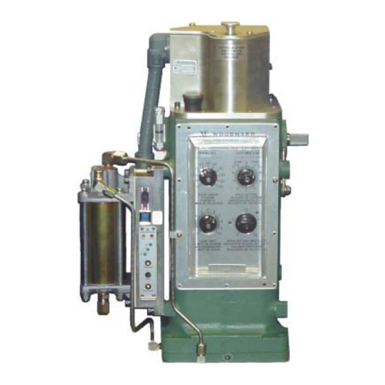
Page 10: Figure 1.1 Outline Drawing Of
UG40-DI Manual Manual B03575.C Figure 1.1 Outline Drawing of UG40-DI Governor (sheet 1 of 2) Woodward... - Page 11 Manual B03575.C UG40-DI Manual Figure 1.1 Outline Drawing of UG40-DI Governor (sheet 2 of 2) Woodward...
-
Page 12: Esd Protection And Handling
UG40-DI Manual Manual B03575.C ESD PROTECTION AND HANDLING CAUTION All electronic equipment is static-sensitive, some components more than others. To protect these components from static damage, you must take special precautions to minimize or eliminate electrostatic discharges. Follow these precautions when working with or near the control. -
Page 13: Description
UG40-DI Manual DESCRIPTION Introduction This Chapter describes the mechanical and digital interface parts of the UG40-DI governor. The mechanical part is the same as the mechanical part on the UG Dial governor series. DI Control Panel and Governor Dial Plate Figure 3.1 DI Control Panel and Governor Dial Plate... - Page 14 Oil flow is directed through the check valve system into the accumulator system (11). 3.3.2.2 Accumulator The accumulator (11) stores oil under pressure for the operation of the UG40-DI governor. The accumulator (two cylinders) also acts as a pressure-relief valve if oil pressure increases above a set level.
-
Page 15: Figure 3.2 Schematicd
Manual B03575.C UG40-DI Manual Figure 3.2 Schematic Diagram of the UG40-DI Woodward... - Page 16 UG40-DI Manual Manual B03575.C The bottom of the power piston has a larger area than the top of the piston. Therefore, less oil pressure is needed on the bottom than on the top to maintain the piston stationary. If the oil pressure is the same on both the top and bottom of the piston, the piston moves up to rotate the governor output shaft in the increase fuel direction.
- Page 17 Manual B03575.C UG40-DI Manual fuel necessary to bring the engine to the required output to adjust to a decrease or an increase in load. The compensation system creates a small temporary change of speed setting with governor output shaft movement to produce a stabilizing speed droop characteristic in the governor.
-
Page 18: Operation Of The Ug40-Di Mechanical Part
Operation of the UG40-DI Mechanical Part 3.3.3.1 General Information Refer to Figure 3.2 with the text to better understand the operation of the UG40-DI governor. The description that follows is based upon speed changes caused by load changes and speed droop. - Page 19 Manual B03575.C UG40-DI Manual When an increase in load occurs and the same fuel setting is maintained, an increase in load creates a decrease in speed. This generates the following sequence of governor movements: As speed decreases, the centrifugal force of the flyweights (24) decreases and the opposing speeder spring (25) force is now greater than the centrifugal force of the flyweights (24).
-
Page 20: Digital Interface
Speed Setting Knob to distribute load between units. Digital Interface 3.4.1 Introduction The following functions of the UG40-DI are built into the DI part: 1. Speed setting The following speed settings are available: 4 – 20 mA remote speed reference Discrete fixed speed input Discrete raise/lower speed input. -
Page 21: Component Description
3.4.3 Operation Refer to Figure 3.1 DI Control Panel and Governor Dial Plate and Figure 3.2 Schematic Diagram of the UG40-DI. 3.4.3.1 Speed setting Speed setting is controlled by the speed-setting stepper-motor controlled from the Di. The speed-setting assembly contains an absolute feedback potentiometer which provides a feedback signal to the Di. -
Page 22: Installation
Refer to 1.7 Technical Data. Unpacking When you receive your UG40-DI governor it is bolted to a wooden platform in a vertical position. After testing at the factory, the governor is drained of oil which leaves a thin film of oil covering the internal parts, thus preventing rust. -
Page 23: Linkage Attachments
Mount the governor flush with the engine drive pad. If the engine drive pad is at an angle (from 0° to 45° maximum), the UG40-DI must be installed with the front panel facing up. Linkage Attachments This section is only applicable to diesel-powered engines. -
Page 24: Oil Supply
Many automotive and gas engine oils, industrial lubricating oils, and other oils of mineral or synthetic origin meet these requirements. Woodward governors are designed to give stable operation with most oils with the viscosity, at the operating temperature, between 50 and 3000 SUS (Saybolt Universal Seconds). -
Page 25: Figure 4.2 Oil Chart
Manual B03575.C UG40-DI Manual Figure 4.2 Oil Chart Table 4.2 Viscosity Comparisons Saybolt Universal Centistokes Seconds (SUS), SAE Motor SAE Gear (CST, CS or CTS) nominal at (approximate) (approximate) 37.7 °C (100 °F) 1020 1483 2133 WARNING A loss of stable governor control and possible prime mover overspeed may result If the viscosity exceeds the 50 to 3000 SUS range. -
Page 26: Figure 4.3 Oil Drain Plug
UG40-DI Manual Manual B03575.C WARNING Observe manufacturer's instructions or restrictions regarding the use of solvents. If no instructions are available, handle with care. Use the cleaning solvent in a well-ventilated area away from fires or sparks. Failure to follow above safety Instructions can result In dangerous fires, extensive damage to equipment, personal injury and/or loss of life. -
Page 27: Electrical Connections
Manual B03575.C UG40-DI Manual Electrical Connections Figure 4.4 UG40-DI Electrical Connections Woodward... -
Page 28: Governor Mechanical Operation And Adjustments
Initial Operation for a New Governor – Mechanical Before initial operation of the UG40-DI, check that all previous installation steps have been correctly accomplished and all linkages are secure and correctly attached. See 4. INSTALLATION. Also, read all of 5. GOVERNOR MECHANICAL OPERATION AND ADJUSTMENTS. - Page 29 Manual B03575.C UG40-DI Manual Maximum compensation settings generally provide stable steady state operation, but result in greater offspeeds on load changes. After the oil in the governor has reached its normal operating temperature, make the following compensation adjustments without load on the prime mover to be certain that the governor gives optimum control.
-
Page 30: Reading Settings From Mechanical Governor On The Engine
UG40-DI Manual Manual B03575.C Closing the needle valve more than 3/8 turn open makes the governor slow to return to normal speed after a load change. Opening the needle valve more than 3/4 open decreases governor stability and can cause hunting. -
Page 31: Calibration Of The Digital Interface
CALIBRATION OF THE DIGITAL INTERFACE Introduction This chapter describes the calibration of the Digital Interface (Di) of the UG40-DI governor. Before the Di can be calibrated you must first adjust the mechanical part (refer to 5. GOVERNOR MECHANICAL OPERATION AND ADJUSTMENTS). - Page 32 UG40-DI Manual Manual B03575.C Red LED (refer to Table 6.2) In program mode this LED indicates a calibration error or program exit without saving. (In normal operation the LED indicates an alarm.) Table 6.2 Red LED operation LED on When active...
-
Page 33: Calibration On Test Bench
The governor must be mechanically adjusted before calibration is started (refer to 5. GOVERNOR MECHANICAL OPERATION AND ADJUSTMENTS). This procedure is normally done at Woodward. Calibration is done on the test bench. This procedure sets basic values in the Di so it can be adjusted. -
Page 34: Calibration On Engine
0. Enter calibration mode (refer to 6.5 Calibration Flow Chart and 6.2 Functions of UG40-DI During Calibration), and go to the 20% fuel limit. Turn the Load Limit knob clockwise while slowly pushing the terminal shaft until the Load Limit indicator stops moving. - Page 35 Manual B03575.C UG40-DI Manual Calibration Flow Chart Sheet 1 of 2 Start of calibration Install UGDI on test bench. Remove cover assembly cover and disconnect one wire from the solenoid operated stop valve. Supply power to DI. Active the stop solenoid input.
- Page 36 UG40-DI Manual Manual B03575.C Calibration Flow Chart Sheet 2 of 2 Sheet 2 Apply 4.00 mA to the speed setting input. Press short Enter » Mode LED gives flash-code 2. » Max LED is on. Apply 20.00 mA to the speed setting input.
-
Page 37: Adjustment Of The Digital Interface
ADJUSTMENT OF THE DIGITAL INTERFACE Introduction This chapter describes the adjustment of the digital interface of the UG40-DI governor. Before the digital interface can be adjusted you must first adjust the mechanical part (refer to 5. GOVERNOR MECHANICAL OPERATION AND ADJUSTMENTS) and calibrate the digital interface (refer to 6. - Page 38 UG40-DI Manual Manual B03575.C Table 7.1 Adjustment Mode LED flash codes Flash pulse Program mode I….I….I….I….I Menu 1 : Speed setting adjustment. Mode Continuously on (with green program Dial adjustment to 0. LEDs) Mode II….II….II….II….II Menu 2 : Ramp time adjustment.
- Page 39 Manual B03575.C UG40-DI Manual Enter button (refer to Table 7.4) This button is used in two ways: Short enter: Press the enter key for less than 1 second. Long enter: Press and hold the enter key for more than 2 seconds.
-
Page 40: Displaying Values On The Dial Panel Speed Setting Knob And Speed Indicator
The 4 mA and 20 mA speed settings are set. Set zero reference The speed-setting knob is set exactly on 0 to give a reference point for all subsequent settings in adjustment. Note that the UG40-DI temperature can influence the zero position of the speed-setting knob. Set ramp values Sets the lower, raise and upper ramp values. -
Page 41: Procedure
Manual B03575.C UG40-DI Manual 7.3.1 Procedure CAUTION For initial adjustment use the safest settings. Test the settings to determine suitability for the engine then do the adjustment again using more applicable settings. Repeat adjustment until the best settings are determined. - Page 42 UG40-DI Manual Manual B03575.C Adjustment Flow Chart Sheet 1 of 5 Start of adjustment Is UGDI on Install UGDI on test bench. the engine? Disconnect coil wire from stop solenoid. Apply 24 VDC on TB1 terminals 4 Stop the engine and 5.
- Page 43 Manual B03575.C UG40-DI Manual Adjustment Flow Chart Sheet 2 of 5 Sheet 2 CODE I - MID LED » Mode LED gives flash code I » Speed setting knob & indicator show existing 20 mA speed setting » Mid LED comes on.
- Page 44 UG40-DI Manual Manual B03575.C Adjustment Flow Chart Sheet 3 of 5 Sheet 3 NOTE: The DI uses the zero Speed CODE - Set Setting as a reference for menu 2 » Mode LED continuously on zero and 3 inputs during adjustment.
- Page 45 Manual B03575.C UG40-DI Manual Adjustment Flow Chart Sheet 4 of 5 Sheet 4 CODE II - MAX LED » Mode LED gives flash code II » Speed setting knob & indicator shows existing upper ramp rate » Max LED comes on.
- Page 46 UG40-DI Manual Manual B03575.C Adjustment Flow Chart Sheet 5 of 5 Sheet 5 Short ENTER. » Mode LED gives flash code III CODE III - MID LED » Speed setting knob & indicator shows existing clutch fuel limit » Mid LED comes on.
-
Page 47: Fine-Tuning Flow Charts
Manual B03575.C UG40-DI Manual Fine-Tuning Flow Charts 7.6.1 Speed Setting fine-tuning Start of speed setting fine-tune NOTE: Rated speed = 20 mA ± 5% = 19 to 21 mA » Calibrated and adjusted UGDI Idle speed = 4 mA ± 5% = 3 to 5 mA on engine. -
Page 48: Fuel Limit Fine Tuning
UG40-DI Manual Manual B03575.C 7.6.2 Fuel limit fine tuning Start of start fuel limit fine-tune » Calibrated and adjusted UGDI on engine. » Engine stopped. » No clutch limit activated. Press and hold Enter button. When Min LED stops flashing, press Increase button. -
Page 49: Clutch Fuel Limit Fine Tuning
Manual B03575.C UG40-DI Manual 7.6.3 Clutch fuel limit fine tuning Start of clutch fuel limit fine-tune » Calibrated and adjusted UGDI on engine. » Engine running or stopped. » Clutch limit input activated. Press and hold Enter button. When Min LED stops flashing, press Increase button. -
Page 50: Alarms, Diagnostics And Serial Communications
Serial interface Refer to 8.3 UG40-DI Serial Interface It is possible to connect a PC to the UG40-DI serial port. The PC must have a terminal program, for example Microsoft Windows HyperTerminal. Using the terminal program you can monitor the alarm and diagnostics, view internal UG40-DI calibration values and upload new software. -
Page 51: Alarm Flash Codes
Manual B03575.C UG40-DI Manual Blue button (above DI panel) This is the remote speed-setting override button, which disengages the DI speed-setting and returns the governor to mechanical control (for use only in emergency). Red LED (refer to Table 8.1) During normal operation, the red alarm LED indicates active alarms by flashing their corresponding alarm flash codes. -
Page 52: Ug40-Di Serial Interface
UG40-DI Manual Manual B03575.C UG40-DI Serial Interface 8.3.1 Serial link with PC - alarm page When the Increase and Enter buttons are pressed simultaneously, the alarm page is sent through the serial interface. A page similar to Figure 8.1 is received by the terminal program running on the PC. -
Page 53: Serial Link With Pc - Uploading Software
CAUTION Saved hour counter parameters will be reset when the parameter revision of the new software differs from the one currently in the UG40-DI. Only qualified Woodward personnel may upload new software. A PC, a serial cable, and terminal emulation software set up as described in 8.1.2 Serial interface are required. -
Page 54: Figure 8.3 Typical Terminal
LED will flash slowly now, indicating the UG40-DI is ready to receive new software. When the software is sent to UG40-DI, first the green Mid LED comes on. After about one second it goes off and the green Max and Min LEDs flash rapidly indicating that data is being received by the UG40-DI. -
Page 55: Troubleshooting And Repairs
Manual B03575.C UG40-DI Manual TROUBLESHOOTING AND REPAIRS Introduction This section provides instructions for troubleshooting. It is impossible to anticipate every kind of trouble that is encountered in the field. This manual covers the most common troubles experienced. Poor governing may be due to faulty governor performance, or it may be due to the governor attempting to correct for faulty operation of the prime mover or the equipment driven. -
Page 56: Oil
UG40-DI Manual Manual B03575.C To change oil, remove the drain plug and drain out the old oil. Flush the governor by filling it with fuel oil, and with the prime mover running at low speed, cycle the governor by opening the needle valve two or three turns. -
Page 57: Trouble-Shooting Chart
Manual B03575.C UG40-DI Manual 9.3.2 Trouble-shooting chart Table 9.1 Troubleshooting Chart Trouble Cause Correction 1. The engine, turbine or A. The trouble may be Block the throttle, fuel racks or other type of prime mover originating in the governor or steam valve in the direction of hunts or surges. - Page 58 UG40-DI Manual Manual B03575.C Trouble Cause Correction I. Spring on yield linkage to Install heavier spring. fuel racks too weak J. Low oil pressure. Normal Return governor to factory for operating pressure is 240 to repair. 250 PSI. (See Outline Drawing, Figure 1.1 for...
- Page 59 Manual B03575.C UG40-DI Manual Trouble Cause Correction 2. Fuel racks do not quickly A. Low oil pressure in See item 1.J. above. when open cranking governor. engine, turbine or other type of prime mover. B. Cranking speed too low. May be necessary to use a booster servomotor.
- Page 60 UG40-DI Manual Manual B03575.C Trouble Cause Correction B. Speed settings of the Adjust speed setting so both governors are not the same. prime movers run at the same speed. 5. The engine, turbine or A. Needle valve adjustment Readjust compensating needle other type of prime mover incorrect.
-
Page 61: Governor Field Repairs
Seals and bearings can be replaced without these tools, however replacement of parts is made easier if these tools are available. Order tools from the Woodward Governor Company, Fort Collins, Colorado (see address on the back cover of this manual). Include in order: The tool description. -
Page 62: Returning The Ug40-Di To Woodward
Returning the UG40-DI to Woodward If you have to return the UG40-DI governer to Woodward please complete the form on the following page. Make sure the governer is suffciently packaged to prevent it from damage. Include the form in the package with the governor. - Page 63 Manual B03575.C UG40-DI Manual General Your Name Your Address Site Location Phone Number Fax Number Prime Mover Information Engine/Turbine Model Number Manufacturer Number of Cylinders (if applicable) Type of Fuel (gas, gaseous, steam, etc) Rating Application Governor Information Woodward Part Number...
- Page 64 UG40-DI Manual Manual B03575.C Woodward...
- Page 66 World Wide Web Home Page - Registered Firm ISO 9001:1994/Q9001-1994 Certificate QSR-36 Woodward has company-owned plants, subsidiaries, and branches, as well as authorized distributors and other authorized service and sales facilities throughout the world. Complete address/phone/fax/e-mail information for all locations is available on our website.
Need help?
Do you have a question about the UG40 and is the answer not in the manual?
Questions and answers