Table of Contents
Advertisement
Quick Links
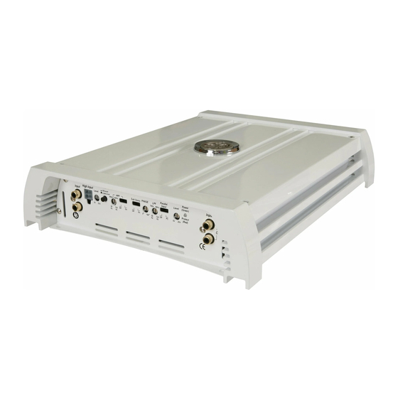
How to install and operate the
DLS Marine Audio amplifiers
MRA22
MRA31
MRA41
Welcome!
This owners manual is written in easy english and
uses a lot of drawings to simply the installation and
use of the above amplifiers.
Your DLS amplifiers must be installed correctly in
order to work well. This manual will show you how
to install the amplifier like a pro. Please read the
entire manual before beginning the installation.
Install the amplifier yourself if you feel confident with
our instructions and if you have the proper tools.
However if you feel unsure, turn over the installa-
tion job to someone better suited to it.
Warranty Service
This amplifier is covered by warranty, depending
on the conditions in the country where it is sold. If
the amplifier is returned for service, please include
the original dated receipt with the product.
Technical Assistance
For technical assistance ask the shop where the
product was sold or the distributor in your very
country.You can always phone the DLS Helpdesk in
Sweden+ 46 31 84 00 60 or send an e-mail to
info@dls.se.Information can also be found on our WEB-
site www.dls.se
DLS Svenska AB
P.O. Box 13029
SE-40251 Göteborg, Sweden
Tel: +46 31 840060
Fax: +46 31 844021
E-mail: info@dls.se
www.dls.se
Contents
Installation................................
Tools and materials needed..........
Amplifier installation kit................
Wiring
Power and Remote.....................
Input wiring Hi & Low level...........
Parallel input..................................
Hi/Low input switch........................
Fuses / Protect light.......................
Input level control...........................
Phase control.................................
Crossovers...................................
MRA 22 speaker wiring:
Front speakers............................
Subwoofer.................................
MRA 31 speaker wiring:
Front speakers............................
Subwoofer.................................
MRA 41 speaker wiring:
Four speakers............................
Two speakers + bridged subwoofer.
Two way front system with
active crossover..........................
Testing......................................
Troubleshooting...........................
Professional tips..........................
Specifications.............................. 12
All models include
RCA inputs
High Level input
Continuos variable low pass and high
pass crossover
Remote turn on / off
Automatic remote turn on/ off on high level
input without connecting any remote wire
Electronic protection circuitry against
short-circuit, DC offset and thermal overload.
Bridgeable design to direct full power to
one or two subwoofers etc.
IMPORTANT!
While these amplifiers are specially designed
for marine applications, they are not
waterproof and should not be mounted where
it is likely to get wet.
The cover is made to resist moisture as well
as the PC-board.
2
3
3
3
4
4
4
4
5
5
5
6
6
7
7
8
8
9
10
10
11
Advertisement
Table of Contents

Related Manuals for DLS MRA22 - MANUAL 2


Summary of Contents for DLS MRA22 - MANUAL 2
-
Page 1: Table Of Contents
Front speakers…...………………..use of the above amplifiers. Subwoofer…………………………... Your DLS amplifiers must be installed correctly in MRA 41 speaker wiring: order to work well. This manual will show you how Four speakers…………………….. -
Page 2: Installation
The DLS logo on top of the amplifier is attached installed electronic devices. You should also take with two 1 mm hex. screws. The logo can be remo-... -
Page 3: Tools And Materials Needed
To head unit extra for fuse holder. remote Electrical insulation tape DLS FH1 fuse holder Amplifier installation kit: Connect the battery cable by a crimp fork terminal If available, buy an amplifier installation kit. It (spade ) to the +12 Volt on the amplifier. -
Page 4: Power And Remote
MRA22, MRA31, MRA41 Input and controls MRA41 High level input sockets The MRA41 four channel amplifier is connected Input Wiring likewise, however we have four channels. You can feed two channels from RCA and two Inputs may be low level from the RCA output of the car channels using high level input from rear speaker stereo or high level from the car stereo speaker out- cables. -
Page 5: Input Level Control
MRA22, MRA31, MRA41 Input Level control Low Pass Filter (LPF) The input level control, 5V – 0,25 V, Filter frequency range: matches the output of your radio to Level MRA22: 50-500 Hz 80Hz 200Hz MRA31: 50 - 120 Hz the input of the amplifier. After instal- MRA41: lation is complete, make sure the in- 50Hz 500Hz... - Page 6 MRA41 The MRA41 is a four channel amplifier. It is mostly The MRA22 is a two channel stereo amplifier. It has used with a front system connected to channels C/ a variable high pass filter, (HPF) 15-500 Hz. It has D and a subwoofer connected to channel A/B.
- Page 7 MRA22 Speaker wiring MRA 22 One subwoofer connected in bridge mode to Two fullrange speakers to MRA22 MRA22 NOTE! 4 ohm minimum load when using bridge mode connection. Lower impedances may damage the amplifier. In bridge mode the amplifier sees a 4 ohm load as 2 ohm.
- Page 8 MRA31 Speaker wiring MRA 31 Two fullrange One (or two) speakers to 4 ohm + C CH - channel A/B subwoofers to channel C A single 2 subwoofer can also be connected. With the HPF-filter in OFF position the amplifier allows 90Hz 120Hz the speakers to play...
-
Page 9: Front Speakers
MRA41 Speaker wiring MRA 41 - three different wiring examples 1. Four fullrange speakers to MRA41. One 2. Two fullrange speakers and one subwoofer pair in front and one pair in rear. to MRA41. Rear speakers Front speakers Rear subwoofer Rear or front speakers Filter settings A/B Channels Filter settings A/B Channels... -
Page 10: Active Crossover
MRA41 Speaker wiring MRA 41 3. One 2-way speaker system to MRA41 using active crossover between tweeter and midrange / bass Midrange Tweeters Filter settings A/B Channels Multiply 50Hz 220Hz 80/800Hz 200/2(k)Hz x1 x10 Off On 15Hz 500Hz 50/500Hz 500/5(k)Hz Off On We want a crossover point of 4 kHz between tweeter and midrange. -
Page 11: Testing
4. Check the amplifier protection fuses. Are these broken change to new ones with the same value. If short circuiting continues, contact your local DLS dealer. A fault may exist in the amplifier. 5. To start the amplifier requires a remote voltage of Test power wiring 9-15 volt. -
Page 12: Professional Tips
NOTE! Tweeters can not be tested this way, double check the connections instead. If noise remains regardless of cable position, try to use so called Quasi-balanced signal cables. DLS PRO-cables are Quasibalanced. Professional Tip: Securing wires Use wire ties to bundle together when possible. -
Page 13: Specifications
MRA22, MRA31, MRA41 Specifications DLS MARINE AUDIO MRA 22 MRA41 Number of channels Power output, 4 ohm (0,1% THD) 2 x 60 W 4 x 70 W Power output, 2 ohm (0,2% THD) 2 x 100 W 4 x 125 W...