Table of Contents
Advertisement
Advertisement
Table of Contents

Related Manuals for IFM PQ3809


Summary of Contents for IFM PQ3809
- Page 1 Operating instructions Pressure sensor PQ3xxx...
-
Page 2: Table Of Contents
Contents 1 Preliminary note ���������������������������������������������������������������������������������������������������3 1�1 Symbols used ������������������������������������������������������������������������������������������������3 2 Safety instructions �����������������������������������������������������������������������������������������������3 3 Functions and features ����������������������������������������������������������������������������������������4 3�1 Use of the main connection G1/8 ������������������������������������������������������������������4 3�2 Use of the auxiliary connection M5 ����������������������������������������������������������������5 4 Function ���������������������������������������������������������������������������������������������������������������5 4�1 Output signals ������������������������������������������������������������������������������������������������5 4�2 Switching function ������������������������������������������������������������������������������������������5 4�3 IO-Link �����������������������������������������������������������������������������������������������������������6 4�3�1 General information ������������������������������������������������������������������������������6... -
Page 3: Preliminary Note
9�3�3 Configuration of the display ����������������������������������������������������������������15 9�3�4 Zero-point calibration ��������������������������������������������������������������������������16 9�3�5 Differential pressure measurement: optimisation of the sensor accuracy �������������������������������������������������������������������������������������������������������16 9�4 Service functions �����������������������������������������������������������������������������������������16 9�4�1 Read min/max values for the system pressure ����������������������������������16 9�4�2 Reset all parameters to factory setting �����������������������������������������������17 10 Operation ���������������������������������������������������������������������������������������������������������17 10�1 Read set parameters ���������������������������������������������������������������������������������17 10�2 Error indications �����������������������������������������������������������������������������������������17... -
Page 4: Functions And Features
• The product must be suitable for the corresponding applications and environmental conditions without any restrictions� • Only use the product for its intended purpose (→ Functions and features). • Only use the product for permissible media (→ Technical data). •... -
Page 5: 3�2 Use Of The Auxiliary Connection M5
3.2 Use of the auxiliary connection M5 Observe the respective notes in these instructions for measurement accuracy optimisation for differential pressure measurements (→ chapter 9�3�5 Differential pressure measurement)� Application: compressed air (other media on request); use for differential pressure measurement; connection of the low pressure side� In particular for filter monitoring, the output side of the filter (i�e�... -
Page 6: 4�3 Io-Link
In addition communication is possible via a point-to-point connection with a USB adapter cable� You will find more detailed information about IO-Link at www�ifm�com� 4.3.2 Device-specific information You will find the IODDs necessary for the configuration of the IO-Link unit and detailed information about process data structure, diagnostic information and parameter addresses at www�ifm�com�... -
Page 7: Installation
5 Installation Before installing and removing the unit: Make sure that no pressure is applied to the system� ► Screw the pressure connection or adapter G1/8 to the main pressure connection (1) and tighten: • Maximum tightening torque: 8 Nm� •... -
Page 8: 5�3 Panel Mounting
5.3 Panel mounting ► Fix the unit with 2 M4 x 35 screws (1) (not included) to the rear panel� Maximum tightening torque: 0�5 Nm� 6 Electrical connection The unit must be connected by a qualified electrician� The national and international regulations for the installation of electrical equipment must be adhered to�... -
Page 9: Operating And Display Elements
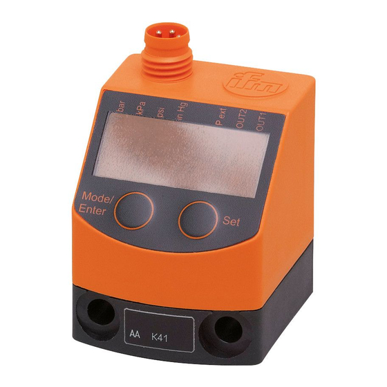
7 Operating and display elements 1 2 3 4 5 6 7 8 Mode/Enter Set 1 to 8: Indicator LEDs - LED 1 to LED 4 = system pressure / differential pressure in the unit of measurement which is indicated on the label� - LEDs 5, 6, 7: not used�... -
Page 10: Menu
8 Menu 8.1 Menu structure... -
Page 11: 8�2 Explanation Of The Menu
8.2 Explanation of the menu SP1/rP1 Upper / lower limit value for system pressure at which OUT1 switches� FH1/FL1 Upper / lower limit for the acceptable range (monitored by OUT1)� Extended functions / opening of menu level 2� Restore factory setting� Switch-on delay for OUT1�... -
Page 12: Parameter Setting
9 Parameter setting During parameter setting the unit remains in the operating mode� It continues to monitor with the existing parameters until the parameter setting has been completed� 9.1 Parameter setting in general 3 steps must be taken for each parameter setting: Select parameter ►... - Page 13 ► Press [Set] and keep it pressed until Mode/Enter Set the valid code no� is displayed� ► Briefly press [Mode/Enter]� When delivered by ifm electronic: no access restriction� ► Briefly press [Set]� > The first parameter of the submenu is displayed (here: [rES])�...
-
Page 14: 9�2 Set Output Signals
9.2 Set output signals 9.2.1 Set the unit of measurement for system pressure ► Select [uni] and set the unit of measurement: [bAr], [kPa], [PSi], [inHg]� 9.2.2 Set the output function ► Select [ou1] and set the function: - [Hno] = hysteresis function/normally open, - [Hnc] = hysteresis function/normally closed, - [Fno] = window function/normally open, - [Fnc] = window function/normally closed�... -
Page 15: 9�3 User Settings (Optional)
9.3 User settings (optional) 9.3.1 Set delay for the switching outputs • [dS1] = time delay for SP1 / FH1� If the system pressure exceeds SP1 or if the system pressure enters the acceptable range (window), the output changes the switching status when the time dS1 has elapsed� •... -
Page 16: 9�3�4 Zero-Point Calibration
9.3.4 Zero-point calibration ► Select [coF] and set a value between -2 % and 2 % of the measuring span� The internal measured value "0" is shifted by this value� As an alternative: Automatic adjustment of the offset in the range 0 bar ± 2 % of the measuring span�... -
Page 17: 9�4�2 Reset All Parameters To Factory Setting
9.4.2 Reset all parameters to factory setting ► Select [rES]� ► Press [Set] and keep it pressed until [----] is displayed� ► Briefly press [Mode/Enter]� We recommend noting down your own settings before carrying out a reset (→ 12 Factory setting). 10 Operation After power on, the unit is in the Run mode (= normal operating mode)�... -
Page 18: Factory Setting
11 Factory setting Factory setting User setting SP1 / FH1 25% VMR * rP1 / FL1 23% VMR * SySP cLor r-on * = the indicated percentage of the final value of the measuring range (VMR) of the corresponding sensor is set in bar... - Page 19 More information at www�ifm�com...
Need help?
Do you have a question about the PQ3809 and is the answer not in the manual?
Questions and answers