
Related Manuals for Inovance IS620NS2R8I


Summarization of Contents
Safety Information and Precautions
Electrical Safety
Emphasizes extreme care when working with servo drives due to high voltages.
Machine/System Design and Safety of Personnel
Outlines responsibilities for safe design, installation, and commissioning.
Electrical Installation - Safety
Details shock risks and precautions for wiring and power supply isolation.
Electrical Shock Hazard
Addresses protective earthing requirements and leakage current considerations.
Approvals
Lists certification marks and their corresponding standards and directives.
Chapter 1 Product Information
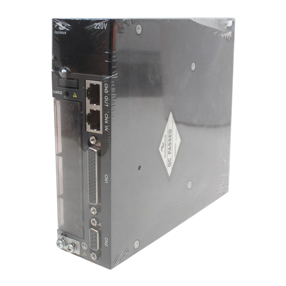
1.1 Servo Drive
Covers designation rules, nameplate, and specifications of the servo drive.
1.2 Servo Motor
Details designation rules, nameplate, and specifications of the servo motor.
1.3 Servo System Configuration
Explains system configuration options for different voltage and motor combinations.
1.4 Environment
Specifies operating and storage conditions for servo drives and motors.
Chapter 2 Wiring
2.1 Servo System Wiring
Provides examples of wiring for single-phase and three-phase systems.
2.2 General Wiring Diagram
Shows a general wiring diagram illustrating connections for various components.
2.3 Cable Model
Lists available cable models for servo motors and connectors.
2.4 Connection Between Servo Drive and Servo Motor
Details terminal arrangements and connections for servo drives and motors.
2.4.1 Main Circuit
Explains the functions of main circuit terminals for different drive sizes.
2.4.2 Servo Motor Encoder
Covers wiring and connectors for serial and absolute encoders.
2.4.3 Control Signal Terminal Connector CN1
Details pin layout and signal descriptions for the control signal connector.
2.4.4 Communication Signal Terminal Connectors CN3/CN4
Defines pin connections for EtherCAT communication ports.
2.4.5 Communication Signal Terminal Connector CN5
Details pin definitions for background communication and online upgrade.
Chapter 3 Operation and Display
3.1 Introduction to Keypad
Describes the servo drive keypad, its components, and key functions.
3.2 Keypad Display
Explains the information displayed on the keypad and its various modes.
3.2.1 Conversion Between Keypad Display and Host Controller Operation Objects
Details the mapping between keypad parameters and object dictionary entries.
3.2.2 Display Switchover
Explains how to switch between different display modes on the keypad.
3.3 Parameter Setting
Outlines methods for setting drive parameters via host controller or keypad.
3.4 User Password
Describes how to set, modify, and cancel user passwords for security.
Chapter 4 Quick Setup
4.1 Inovance PLC AM600 as Master
Guides on controlling IS620N servo drives using an Inovance AM600 PLC.
4.1.1 Controlling a Single Drive
Step-by-step instructions for controlling one IS620N servo drive with AM600.
4.1.2 Controlling Two Drives
Instructions for controlling two IS620N servo drives with an AM600 PLC.
4.2 Omron PLC NJ501 as Master
Guide for controlling IS620N servo drives using an Omron NJ501 PLC.
4.2.1 Making Preparations
Details software installation, device description import, and network setup.
4.2.2 Configuring the Servo Drive
Steps to set servo drive parameters, including station alias and synchronization mode.
4.2.3 Configuring Omron NJ Software
Steps for project creation, communication setup, device scanning, and parameter configuration.
Chapter 5 Troubleshooting
5.1 Fault and Warning Rectification at Startup
Lists startup faults, probable causes, and methods for confirmation and rectification.
5.2 Troubleshooting of Faults
Details troubleshooting for various fault codes like Er.101, Er.102, Er.103, etc.
5.3 Internal Faults
Lists internal faults like Er.602, Er.220, Er.A40, Er.111, requiring technical support.
5.4 Rectification of Communication Faults
Provides solutions for communication faults such as Er.D09, Er.D10, Er.E08, Er.E11.
Chapter 6 Overview of Object Dictionary
6.1 Object Group 1000h
Lists parameters for CANopen communication related to Sync Manager.
6.2 Object Group 2000h
Details servo motor and servo drive parameters, including control mode.
6.2 Object Group 2002h
Lists parameters for basic control settings.
6.2 Object Group 2003h
Lists parameters for input terminals (DI) and their logic selection.
6.2 Object Group 2004h
Details parameters for output terminals (DO) and analog signals (AO).
6.2 Object Group 2005h
Covers parameters for position control, including homing and gear ratio.
6.2 Object Group 2006h
Lists parameters for speed control, including jog speed and torque feedforward.
6.2 Object Group 2007h
Details parameters for torque control, including limits and filters.
6.2 Object Group 2008h
Lists gain parameters for speed and position loops, and switchover settings.
6.2 Object Group 2009h
Covers automatic gain tuning parameters, resonance suppression, and inertia tuning.
6.2 Object Group 200Ah
Details fault and protection parameters, including phase loss and overspeed.
6.2 Object Group 200Bh
Lists monitoring parameters for speed, current, voltage, and fault records.
6.2 Object Group 200Ch
Covers communication parameters, including EtherCAT settings and serial baud rate.
6.2 Object Group 200Dh
Lists auxiliary function parameters like software reset, fault reset, and jog function.
6.2 Object Group 200Fh
Details parameters for fully closed-loop operation and encoder feedback modes.
6.2 Object Group 2017h
Covers VDI (Input) and VDO (Output) function and logic selections.
Need help?
Do you have a question about the IS620NS2R8I and is the answer not in the manual?
Questions and answers