
Related Manuals for golmar ART 7


Summarization of Contents
Recommendations and System Operation
Recommendations
Key advice for optimal system performance and installation.
System Operation
Explains how the video door entry system functions during calls and communication.
FA-G2+ Power Supply
Description
Details the components and indicators of the FA-G2+ power supply unit.
Installation
Provides instructions for safely installing the FA-G2+ power supply.
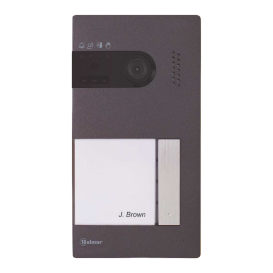
Soul Panel
Description
Identifies and explains the various parts and features of the Soul panel.
Installation
Details the physical mounting and connection steps for the Soul panel.
Soul Panel Installation Terminals
Installation Terminals
Explains the connection points for the Soul panel's installation terminals.
Soul Panel Configuration and Settings
Configuration Switches
Describes how to set up the Soul panel using its configuration switches.
Setting Audio Level
Instructions on adjusting the audio volume using the potentiometer.
Soul Panel Proximity Reader Programming
Programming Proximity Reader
Guide to programming user keys and managing the proximity reader.
Art 7/G2+ Monitor Description
Description
Details the components, buttons, and indicators of the Art 7/G2+ monitor.
Art 7/G2+ Monitor Installation and Configuration
Installation
Provides instructions for mounting and connecting the Art 7/G2+ monitor.
Installation Terminals
Explains the connection points for the Art 7/G2+ monitor's installation terminals.
Configuration Switches
Details how to configure the Art 7/G2+ monitor using its DIP switches.
Art 7/G2+ Monitor Main Menu
Main Menu
Navigating the main menu and using hidden buttons for various functions.
Art 7/G2+ Monitor Settings Menu (Part 1)
Settings Menu
Accessing and modifying monitor settings like date, time, and presentation format.
Art 7/G2+ Monitor Settings Menu (Part 2)
Settings Menu
Adjusting melody, call volume, and other system settings via the settings menu.
Art 7/G2+ Monitor Settings Menu (Part 3)
Settings Menu
Managing image/video recording, internal memory, and SD card settings.
Art 7/G2+ Monitor Settings Menu (Part 4)
Settings Menu
Deleting recorded images/videos, formatting SD card, and managing 'Do not disturb' mode.
Art 7/G2+ Monitor Settings Menu (Part 5)
Settings Menu
Configuring automatic door opening, intercom settings, and restoring factory defaults.
Art 7/G2+ Monitor Door Panel Call Screen
Door Panel Call Screen
Understanding the display and controls during a door panel call.
Art 7/G2+ Monitor Communication Screen
Communication Screen
Interacting with the monitor during an active communication session.
Art 7/G2+ Monitor Image and Communication Settings
Image and Communication Settings
Adjusting brightness, contrast, colour, and volume during communication.
Art 7/G2+ Monitor Intercom Menu (Part 1)
Intercom Menu
Making internal and external intercom calls between monitors.
Art 7/G2+ Monitor Intercom Menu (Part 2)
Intercom Menu
Detailed steps for internal and external intercom calls and communication.
Art 7/G2+ Monitor Recordings Menu (Part 1)
Recordings Menu
Accessing and viewing recorded images and videos from the monitor.
Art 7/G2+ Monitor Recordings Menu (Part 2)
Recordings Menu
Viewing, deleting, and managing recorded videos and images.
Art 7/G2+ Monitor Recordings Menu (Part 3)
Recordings Menu
Returning from the recordings menu to the main menu.
Wiring Diagrams
Cross Sections and Distances
Specifies cable types, maximum distances, and monitor limits.
One Apartment with One Access Panel and One Monitor
Wiring diagram for a basic system with one door panel and one monitor.
Wiring Diagrams: Single Apartment Configurations
One Apartment with up to Two Access Panels and Four Monitors in Cascade
Wiring configuration for cascading multiple monitors with two door panels.
One Apartment with up to Two Access Panels and Four Monitors in Distribution
Wiring diagram for distributing multiple monitors with two door panels.
Wiring Diagrams: Dual Apartment Configurations
Two Apartments with up to Two Access Panels and up to Four Monitors in Cascade
Wiring for a dual-apartment system with cascaded monitors.
Wiring Diagrams: Four Apartment Configurations (Part 1)
Four Apartments with up to Two Access Panels and up to Four Monitors in Cascade
Wiring diagram for a four-apartment system with cascaded monitors.
Wiring Diagrams: Four Apartment Configurations (Part 2)
Four Apartments with up to Four Access Panels and up to Four Monitors in Cascade
Wiring for a four-apartment system with multiple door panels and cascaded monitors.
Wiring Diagrams: Connections
Connection of a Lock Release
Diagrams showing how to connect a 12Vdc or AC lock release.
Connection of an Auxiliary Device at the Relay Output
Wiring example for connecting an auxiliary device to the relay output.
Wiring Diagrams: Additional Connections
Connection of an Exit Button
How to wire an exit button for remote lock release activation.
Connection of an External Camera
Instructions for connecting an analogue CCTV camera to the door panel.
Connection for an Apartment Door Button
Wiring an apartment door button to the master monitor.
Special Codes
'About' Screen
Accessing the 'About' screen to enter special codes for configuration.
'Special Codes' Screen
Screen for entering specific codes to enable/modify functions.
Special Codes: Monitor Configuration
Video Sources Available on a Monitor
Configuring which video sources are visible or not on the master monitor.
Automatic Door Opening Upon Reception of a Call
Enabling or disabling automatic door opening when a call is received.
Activation Times of the Outputs (Door Panel 1)
Setting the activation duration for lock release and relay outputs on Door Panel 1.
Special Codes: Advanced Settings
(*) Activation Times of the Outputs (Door Panel 3)
Setting activation duration for outputs on Door Panel 3.
Night Vision Illumination LEDs (Door Panel 1)
Configuring night vision LEDs for Door Panel 1 during calls.
Activate/Deactivate the Ring Tone (Door Panel 1)
Activating or deactivating the ring tone for Door Panel 1.
Need help?
Do you have a question about the ART 7 and is the answer not in the manual?
Questions and answers