Table of Contents
Advertisement
Advertisement
Table of Contents

Related Manuals for jcb 210LC


Summarization of Contents
Intended Use
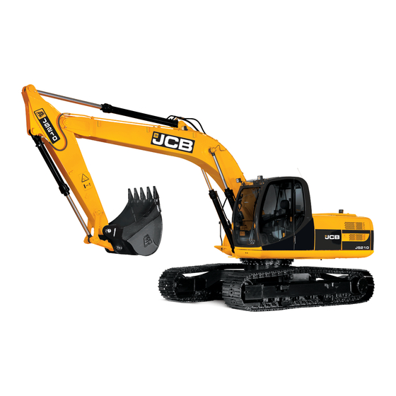
General Machine Description
Specifies the machine as a heavy excavator with a tracked undercarriage and 360° revolving upper structure.
Approved Applications
Outlines intended uses like earthmoving, road construction, and building, with limitations.
Usage Restrictions
Warns against improper use like forestry, unknown attachments, or unstable surfaces to prevent overturning.
Static Dimensions
Machine Dimensions Table
Provides detailed measurements for different undercarriage options and boom configurations.
Boom Option Dimensions
Lists transport length and height for Mono and TAB boom options.
Tie Down Points (Standard Undercarriage)
Fig 2 Diagram
Illustrates undercarriage and dipper tie down points on the machine.
Standard Undercarriage Tie Down
Details tie down points for standard undercarriage configurations with diagrams.
Tie Down Points (Dozer Option)
Fig 3 Diagram
Shows tie down points for undercarriage dozer option.
Dozer Option Angles
Specifies angles for tie down points on the dozer undercarriage.
Tie Down Point Capacities
Lists front and rear tie down point capacities for various undercarriage types.
Lifting Points
Fig 4 Diagram
Illustrates correct lifting points and decals on the machine.
Lifting Decals
Identifies lifting positions using decals (B) as shown in the diagram.
Cab Layout & Controls
Fig 5 Diagram
Diagram showing the layout of controls and components within the operator's cab.
Control Descriptions
Lists and describes various controls including joysticks, keypad, and ignition switch.
Instrument Panel
Fig 6 Diagram
Illustrates the main instrument panel display with labeled indicators.
Fig 7 Diagram
Shows the fuel gauge display with warning band, main band, and needle.
Instrument Panel Indicators
Details indicators for ambient temperature, clock, machine hours, RPM, fuel, coolant, and DEF levels.
Rotary Controller I
Fig 8 Diagram
Diagram of Rotary Controller I with labeled controls.
Rotary Controller Functions
Explains functions like media control, engine start/stop, wiper control, worklight control, powerband, and HVAC.
Rotary Controller 2
Fig 9 Diagram
Diagram of Rotary Controller 2 with labeled buttons.
Rotary Controller 2 Functions
Describes buttons for quick hitch, lift mode, overload warning, and lock/unlock.
Keypad I
Fig 10 Diagram
Diagram of Keypad I with labeled buttons.
Keypad I Functions
Details buttons for slew lock, beacon, camera, controls isolate, travel speed, and engine auto idle.
Keypad 2
Fig 11 Diagram
Diagram of Keypad 2 with labeled buttons and immobiliser keys.
Keypad 2 Functions
Explains functions for call accept, boom float, exhaust filter, aux controls, and slew smoothing.
LH Joystick Controls
ISO Control Pattern Operation
Details the functions of the Left Hand Joystick in ISO control pattern, including slew and dipper control.
RH Joystick Controls
ISO Control Pattern Operation
Details the functions of the Right Hand Joystick in ISO control pattern, including boom, bucket, and tracking control.
Track Levers and Pedals
Operation Overview
Explains the operation of track levers and travel pedals.
TAB Boom Controls
System Operation
Describes the controls for the Triple Articulated Boom (TAB) system.
Start Up Sequence
Key Ignition and Isolation
Covers inserting the isolator key, checking the isolation lever, and engaging the seat belt.
Engine Start and Immobiliser
Details engine pre-heat, disarming the immobiliser, and starting the machine.
Hydraulic Activation
Explains raising the LH isolator lever and pressing the 2 GO button to activate hydraulics.
Shutdown and Auxiliary Venting
Shutdown Sequence
Steps for safely parking, leaving, securing, and isolating the machine.
Auxiliary Venting Procedure
Procedure for venting auxiliaries within one minute of shutdown.
Hydraulic Quick Hitch
Standard Attachment Operation
Steps for unlocking, confirming, and removing standard attachments.
Changing Attachments
Process for engaging and locking attachments using the hydraulic quick hitch.
Specialised Attachment Handling
Specific procedures for crowd override and removing specialised attachments.
Lifting Mode
Mode Selection and Power Band
Activating lift mode and adjusting the power band.
Overload Alarm System
Details the automatic overload warning alarm and its display indicator.
Autoidle and Lift Mode Deactivation
Explains autoidle deactivation in lift mode and how to disable lift mode.
Maintenance Position
Fig 16 Diagram
Diagram showing the excavator in the maintenance position.
Maintenance Position Steps
Procedure for parking the machine, lowering parts, stopping the engine, and isolating the battery.
Service/Maintenance Schedule
Daily Checks (10h)
List of daily checks including attachments, bodywork, engine, fluids, and operations.
Weekly Checks (50h)
List of weekly checks including slew ring bearing, cooling pack, tracks, wiring, and battery.
Service & Maintenance Points - Fig 17-19
Fig 17 Component Locations
Identifies air filter, fuse box, batteries, battery isolator, washer fluid, and radiator.
Fig 18 Fluid Locations
Locates fuel filters, sedimenter, oil level indicator, fuel tap, and water separator.
Fig 19 Cab Filter Location
Shows the location of the fresh air cab filter.
Service & Maintenance Points - Fig 20-21
Fig 20 Fluid Filler Caps & Gearbox
Identifies fluid filler caps, gearbox fillers, and blower booster filter.
Fig 21 Maintenance Cover
Shows the cover, handle, and lock for maintenance access.
Service & Maintenance Points - Access
Upper Step - DEF Filler Access
Procedure for accessing the DEF filler cap via the upper step.
Lower Step - Toolbox/Refuel Pump Access
Accessing the toolbox and refuel pump via the lower step.
Fluids and Lubricants
Fuel and DEF Specifications
Details capacity, JCB part number, and specifications for fuel and DEF.
Engine and Cooling System Fluids
Specifies engine oil types, capacities, and coolant requirements.
Gearbox, Hydraulic, and Grease Types
Lists lubricants for track/slew gearboxes, hydraulic system, and greasing points.
Troubleshooting/FAQs
Machine Will Not Start
Troubleshooting steps for when the machine fails to start, including immobiliser checks.
Cannot Activate Hydraulics
Solutions for activating hydraulics, including isolation lever and 2 GO system checks.
2Go System Status
Information on how to identify if the hydraulic 2Go system is enabled or disabled.
Common Troubleshooting Issues
Quickhitch and Load Warning
Answers regarding quickhitch operation with attachment on ground and audible buzzer during lifting.
Greasing Procedures
FAQs about 250-hour greasing intervals, daily greasing, and bush replacement.
Joystick Patterns and Bluetooth Pairing
Guidance on switching ISO/SAE joystick patterns and pairing a phone via Bluetooth.
Need help?
Do you have a question about the 210LC and is the answer not in the manual?
Questions and answers