Table of Contents
Advertisement
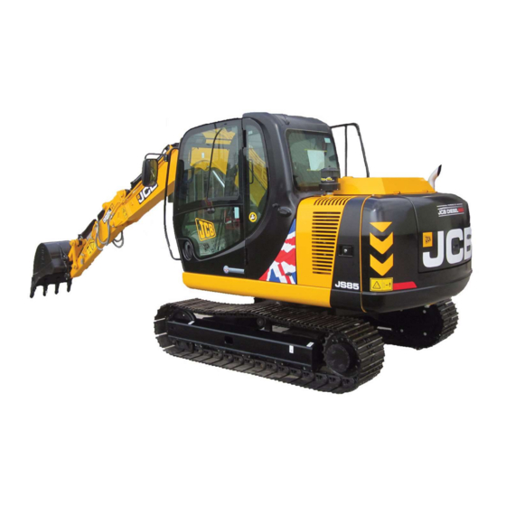
Service Manual
JS Auto Range - Tracked Excavators
JS85
Section 1 - General Information
Section 2 - Operator’s Manual
Section B - Body and Framework
Section C - Electrics
Section E - Hydraulics
Section F - Transmission
Section J - Track & Running Gear
Section K - Engine
Publication No.
9813/3750-01
World Class
Customer Support
Copyright © 2004 JCB SERVICE. All rights reserved. No part of this publication may be reproduced, stored in a retrieval system, or transmitted in any form or by any other means,
electronic, mechanical, photocopying or otherwise, without prior permission from JCB SERVICE.
Issued by JCB Technical Publications, JCB Aftermarket Training, Woodseat, Rocester, Staffordshire, ST14 5BW, England. Tel +44 1889 591300 Fax +44 1889 591400
Advertisement
Table of Contents


Need help?
Do you have a question about the JS Series and is the answer not in the manual?
Questions and answers