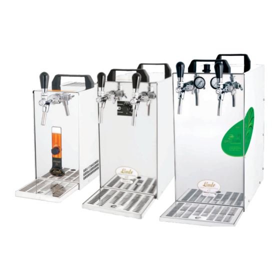
Summarization of Contents
General Instructions and Safety
Safety Instructions
Respect basic safety instructions and take care of personal safety. Cooling equipment is designed for flow type cooling.
Intended Use Only
Machine must only be used for its intended purpose as a flow type cooler for beverages.
General Safety Rules and Precautions
Covers electrical safety, handling precautions, and operational rules to prevent hazards.
Installation and Placement
Initial Placement and Settling
Place cooler on a firm, horizontal surface and allow it to settle for 2 hours before first use.
Handling and Transport Safety
The cooler must not be placed on its side, even during transportation.
Environmental and Location Requirements
Use machine in a cool, well-ventilated room, avoid heat sources and direct sunlight.
Dispensing Tap and Line Connections
Tap Assembly and Securing
Assemble tap, secure cap nut, and tighten with the supplied key.
Beverage and Air Coupler Fittings
Screw appropriate plastic fittings onto beer outlet and air inlet couplers.
Beverage and Air Line Connection
Connect beverage and air lines using specified fittings and tubes to the cooler.
Non-Return Valve Check
Verify the presence of a silicone non-return valve on the air inlet keg coupler.
Pressurization Connection Types
Connection A: Inbuilt Compressor (One Tap)
Diagram and list for connecting a machine with an inbuilt compressor and one dispensing tap.
Connection B: Mini CO2 Bottle (One Tap)
Diagram and list for connecting a machine with a mini CO2 bottle and one tap.
Connection C: Built-in Compressor (Two Taps)
Diagram and list for using a built-in compressor to pressurize machines with two taps.
Advanced Pressurization Options
Connection D: CO2 Bottle (Two Taps)
Diagram and list for connecting a machine with two taps and a CO2 bottle.
Connection E: CO2/N2 Reduction (CONTACT 115R)
Connecting CONTACT 115R to CO2 bottle or mixed gas (CO2 and N2).
CONTACT 115/R to CO2 Bottle Regulation
Steps for connecting and regulating the CONTACT 115/R to a CO2 bottle.
Operation and Maintenance
Connection Sealing Check
Verify all connections are properly sealed before operation.
Electrical Connection Requirements
Machine requires 220-240V 50Hz with 16A circuit breaker and compliant installation.
Tube Connection and Disconnection
Proper methods for inserting and removing tubes from fittings to avoid damage.
Temperature and Thermostat Settings
Manual temperature control via thermostat (1-7) for optimal beverage cooling.
Sanitation Procedures
Regular and Chemical Sanitation
Rinse beverage tube after each use and chemically sanitize every two months.
Chemical Sanitizing Steps
Detailed process for chemical sanitizing using a sanitizing bottle and solution.
Cleaning with Water
Using a cleaning adapter to flush the system with water after use.
Disassembly of Compensator from Tap
Steps to disassemble the tap's compensator for thorough cleaning.
Troubleshooting Common Problems
Beverage Flow Issues
Addresses problems like no beverage flow or insufficient air pressure.
Cooling Performance Problems
Solutions for beverage not being cooled enough or machine overheating.
Pressure and Foaming Issues
Troubleshooting high pressure, compressor not switching, and excessive foaming.
Fitting and Tube Issues
Resolving problems with fittings not sealing properly or damaged tubes.
Model Technical Specifications
Performance and Compressor Details
Table detailing output performance, built-in compressor, and temperature specifications for various models.
Power, Refrigerant, and Weight
Specifications for power supply, refrigerant type, and model weights.
Dimensions and Cooling Coils
Cabinet dimensions (width, height, depth) and length of cooling coils for each model.


Need help?
Do you have a question about the KONTAKT 40/ K and is the answer not in the manual?
Questions and answers