Table of Contents
Advertisement
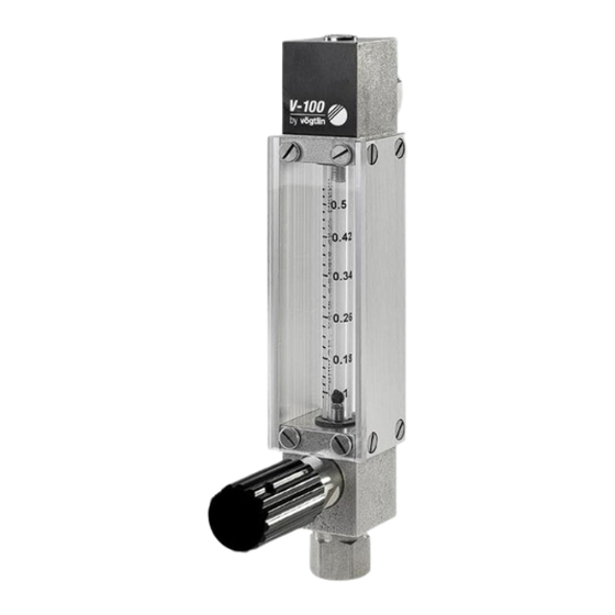
V-Flow Line operating instructions
Variable area flowmeters
Handbuch PCU1000
and high-precision control valves
for gases and liquids
Vögtlin Instruments AG – flow technology
Langenhagstrasse 1 | 4147 Aesch (Switzerland)
Phone 41 (0)61 756 63 00 | Fax +41 (0)61 756 63 01
www.voegtlin.com | info@voegtlin.com
Advertisement
Table of Contents

Related Manuals for Vogtlin V-100 55


Summarization of Contents
Introduction and Product Overview
Service and Quality Commitment
Highlights commitment to continuous product improvement and customer satisfaction, emphasizing high quality and service.
General Information
Operating Principle of Variable Area Flowmeters
Explains the float measuring principle used in variable area flowmeters, detailing force balance for flow indication.
Type Marking Conventions
Details the instrument type label for Q-Flow and V-100, explaining format and key information on the label.
Technical Data and Specifications
Q-Flow Specifications
Provides detailed technical data, materials, and installation setups for Q-Flow series variable area flowmeters.
V-100 Specifications
Presents technical data, materials, and installation setups for V-100 series variable area flowmeters.
M-Flow Specifications and Options
Covers technical data, materials, setups, and valve operation options for M-Flow high-precision control valves.
Measuring Ranges
Direct Reading Scales (Air/Water)
Lists measuring ranges for variable area flowmeters using direct reading scales for Air (In/h) and Water (l/h) under specified conditions.
MM-Scale and Cv-Value Data
Details mm-scale measuring ranges for Q-Flow/V-100 and Cv-values for M-Flow control valves.
Installation and Commissioning
General Installation Guidance
Offers general instructions on instrument design, control valve placement, and scale selection for optimal installation.
Installation Procedures and Connections
Provides step-by-step installation instructions, commissioning steps, and recommended connection types for reliable operation.
Mounting Methods
Describes panel mounting for Q-Flow and faceplate mounting for V-100, including necessary dimensions and kits.
M-Flow Digiturn Installation
Digiturn Installation Steps
Details the step-by-step process for installing the Digiturn on M-Flow valves, including adjustments and securing the components.
Limit Indicators
Limit Indicator Operation and Wiring
Explains limit indicator design, initiator position, switching status, and provides the wiring diagram for setup.
Setting, Spacing, and Applications
Details how to set limit indicators, required spacing, and their application areas on steel variable area flowmeters.
Disassembly and Maintenance
Flowmeter Disassembly
Guides users through the safe disassembly of Q-Flow and V-100 variable area flowmeters, including component removal and refitting.
M-Flow Digiturn Disassembly
Explains the procedure to safely dismantle the Digiturn knob assembly from the M-Flow valve.
Maintenance, Cleaning, and Returns
Covers instrument maintenance, symptoms of soiling, cleaning procedures, and the process for returning devices for service.
Appendix
Dimensional Data
Presents dimensional drawings and tables for Q-Flow, V-100, and M-Flow instruments, including fitting details and thread depths.
Type Code Configurations
Details the type code structure and various options for Q-Flow, V-100, and M-Flow instruments for configuration and ordering.
Contamination Declaration
Declaration Form and Procedures
Provides the official form and instructions for declaring contamination status and hazards when returning devices for service or repair.
Change Log
Document Revision History
Lists the version history of the manual, detailing updates, revisions, and page changes over time.
Need help?
Do you have a question about the V-100 55 and is the answer not in the manual?
Questions and answers