Table of Contents
Advertisement
Quick Links
Thermal Mass Flow Meters and
Manual Regulators for Gases
red-y compact series operating instructions (For serial
number>300000)
Operating instructions
red-y compact 2 series (Serial Number
>300000)
red-y compact meter GCM red-y compact regulator GCR
red-y compact meter with alarm module GCS red-y compact
regulator with alarm module GCA
This manual is updated for the latest firmware version of the red-y compact 2. Please verify
that your unit is updated with firmware version 3.0.6 available from our website (see chapter
5.12 Firmware
upgrade).
Version: red-y compact 2 series EN A2-2
For the latest information on our products, see our website at
© 2019 Vögtlin Instruments GmbH, Switzerland
Copyright and Liability Disclaimer
All rights reserved. No part of this publication may be reproduced in any form or by
any means without the publisher's prior written permission.
The content of this manual is provided for information only and may be altered
without prior notice. Vögtlin Instruments GmbH assumes no responsibility or liability
for any errors or inaccuracies in this manual.
This symbol alerts the user to important operating, maintenance and
service information.
Important instructions
Do not remove the electronics housing. A damaged hologram seal will void the
warranty.
There are no serviceable parts inside the unit.
Repairs must only be performed by qualified personnel
Attention
This unit has several power supply possibilities. If you use the external 24 Vdc power
supply, it is strongly recommended to have this device grounded.
Langenhagstrasse 1 | 4147 Aesch (Switzerland)
Phone +41 (0)61 756 63 00 | Fax +41 (0)61 756 63 01
www.voegtlin.com | info@voegtlin.com
www.voegtlin.com
Vögtlin Instruments GmbH
Advertisement
Table of Contents

Related Manuals for Vogtlin Red-y Compact 2 Series


Summary of Contents for Vogtlin Red-y Compact 2 Series
- Page 1 firmware version 3.0.6 available from our website (see chapter 5.12 Firmware upgrade). Version: red-y compact 2 series EN A2-2 For the latest information on our products, see our website at www.voegtlin.com © 2019 Vögtlin Instruments GmbH, Switzerland Copyright and Liability Disclaimer All rights reserved.
- Page 2 Subject to change Due to our policy of ongoing product development, we reserve the right to change the information in this manual without notice. Recycling Note the existing regulations of your country. Toxic, flammable gases and ATEX In the case of toxic and flammable gases, the respective safety guidelines in each country must be followed.
-
Page 3: Table Of Contents
before you disconnect terminal connections in potentially dangerous surroundings to avoid sparks. Table of contents 1. Introduction 1.10. Features of red-y compact 2 thermal mass flow meters 1.11. Scope of warranty 1.12. Instructions and warnings 1.13. Documentation and cables supplied 1.14. -
Page 4: Introduction
6.14. Dimensional drawings ½” in mm 51 6.15. Dimensional drawings ½” in inches 52 6.16. Type code overview 53 6.17. Wetted parts red-y compact 2 series 54 6.18. Contamination statement 55 6.19. Overview Default settings 56 6.20. CE Declaration of Conformity 58 6.21. -
Page 5: Scope Of Warranty
Integrated temperature compensation and flow totalizer (standard) Easy to maintain and service Firmware upgradable through USB connection 3-year warranty 1.11. Scope of warranty Warranty for the red-y compact product line extends to material and manufacturing defects only. Maximum warranty covers product replacement free of charge. The following causes of faults/damage are not covered under warranty: Use outside the operating limits Damage due to corrosion... -
Page 6: Real, Standardized And Normalized Flow
If there is no flow, the heat spreads symmetrically in directions T1 and T2. The temperature difference T1-T2 is therefore zero. Flow rates > 0 create a temperature difference. The sensor T1 at the inlet is cooled by the gas flowing past it, and the temperature of the second sensor T2 rises due to the heat drawn from the heating system. - Page 7 □ g/min □ g/h □ kg/min □ kg/h □ lb/min □ lb/h This separation is not only there to find the unit you want to select quicker, it also separated the “Normalized flow” from the “Standardized flow” > Flow > Totalizer >...
-
Page 8: Cmos Technology
flow are NOT the operating conditions. According to the ideal gas law, the gas volume will change by 0.35% per K. Please note that Vogtlin standard uses the following densities for their main 3 gasses: Air: 1.293 gr/m3, N2: 1.2504 gr/m3, O2: 1.429 gr/m3 (All at 0°C and 1013.25 mbar absolute). -
Page 9: General Device Specifications
2. General device specifications Media : Air, O2*, N2*, He, Ar, CO2, H2, CH4, C3H8 (real gas calibration) (other gases and gas mixtures on request) *O2 & N2 are calibrated with air. Accuracy: Eco: ±2.0% of full scale; Ranges > 200 ln/min ±3.0% of full scale Special: ±1.0% of full scale... -
Page 10: Safety
Connection cable: For external power supply: 2 m with loose ends (fly leads) 2.10. Safety Test Pressure: 16 Bara (232 psia) Leak rate to external: 1 x 10⁻⁶ mbar*l/s He Protection class: IP-50 EN 61326-1 2.11. Electrical data for meter GCM and regulator GCR Power supply red-y compact 2 meter &... -
Page 11: Optional Modules
strongly recommend to use the “auto power off” in the menu for battery driven devices (see chapter 4.12.7 Battery auto off) More information on the battery in chapter 3.15 Electrical power supply 3.16 How to replace the battery?. Note 1: When we supply the unit, the “auto power off” will be set to 15 minutes Note 2: The unit can be set to performance mode when powered from the battery, this will strongly increase the battery usage. -
Page 12: Calibration
Relais lifetime > 5 million Inputs 1 + 2 (Opto-couplers): Voltage range (polarity sensitive): 5 – 30 Vdc (@ 5mA max) Min. recommended pulse 100 msec (Sample interval: 20 msec) width 2.16. Calibration Each measuring device is supplied with a factory calibration report. The calibration is traceable to American and/or European standards. -
Page 13: Filter Settings
The response time is time required to display 98% of its final value after a sudden change in flow. This response time for the compact 2 is around 300 ms but is dependent on your filter settings. On battery operation you might experience a slower response time than on external power. -
Page 14: Fittings And Filters
Even when connected to fixed pipework, we recommend that the devices are mounted using the appropriate mounting holes From 50 ln/min, we recommend the following flow-calming sections of straight and unobstructed straight tubing: Inlet: 10 x diameter; outlet: 5 x diameter Use appropriate fittings (see chapter 3.13 Fittings and filters). -
Page 15: How To Replace The Battery
The red-y compact 2 can be provided with power from a standard AA battery or from a common USB micro-B charger that you typically use for the charging of your android phone. There are optional modules by which you can apply a 8 to 30 Vdc external power. -
Page 16: Warm-Up Time
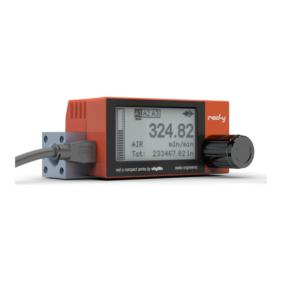
Replace the battery and push the battery compartment back into place. Note that this will not automatically power up the device. You have to press the screen for about 3 seconds in order to power up the device. Please dispose of the battery on an environmental friendly way (Recycle) Figure 7: Battery replacement... - Page 17 Note that the backlight is operational only if the device is powered by an external power supply. 4.10.2. Startup screen During startup the device shows a startup screen (“Sensor mode”). After about 4 seconds the device shows home screens displaying most relevant measurement values.
- Page 18 (drag and move) Swipe right (drag and move) This can also be done via swipe control. Swipe left or swipe right to switch between home screens: It is possible to hide individual home screens (see 4.12.2.1 Home screen). Alarm home screens are only functional when the optional alarm module is installed.
- Page 19 Alarm (if the optional alarm module is installed) Alarm configuration and alarm reset button. Each alarm (A1, A2, A3) has its own home screen. To reset an alarm using the reset button the alarm must be configured for manual reset. 4.10.7.
- Page 20 Touch input). A menu is left by a short press on the back button. The menu can also be left using swipe control (swipe right). Leaving a menu causes its parent menu to be activated again (one level up in hierarchy). Otherwise if there is no parent menu the entire menu is left jumping back to home screens.
-
Page 21: Main Menu
Select a totalizer unit (see 4.12.3 Units) that causes the totalizer value to fit the number of available digits again (for instance m3n or kg). 4.11. Main Menu NOTE: The menu is only available in horizontal mode The home screens are Touch the home Home screen 1 Home screen 2 Home screen 3 Alarm screen A1** Alarm screen A2** Alarm screen A3** All information... - Page 22 Disable Engage Disengage Auto Economy Performance Settings menu Off Medium High Maximum Off Medium High Very high Maximum Disabled 5 seconds 10 seconds 30 seconds 60 seconds 120 seconds Disabled 1 minute 3 minutes 5 minutes 15 minutes 30 minutes Auto 0 degree 180 degree...
- Page 23 > A2: Totalizer > A3: Disabled > Configure > Function Reset Automatic Manual Input 1 Input 2 Text behind alarm are examples only. > Output driver > Reset trigger > Reset source Alarm duration Alarm delay Hysteresis Threshold Flow high Flow low Flow window Totalizer...
- Page 24 Configure In this menu item you can set the details of the alarm like it alarm value(s), how the alarm is reset, Alarms delays, hysteresis and more. For more details see next page. □ Flow high □ Flow low □ Flow window □...
- Page 25 The hysteresis is the difference between the value where the alarm turns ON from turning OFF and the value where it turns OFF from turning ON. This difference is defined in % of full scale. In figure 10 an example of a 50% threshold value high alarm with a 10% hysteresis.
- Page 26 If the blue represents the input being active you can see the different trigger points below. Figure 11: Explanation trigger points Output driver (Default: Normal) □ Normal □ Inverted □ Always low □ Always high The output driver setting offers the possibility to invert the action from the alarm switch and set the alarm to a predefined state which is convenient for testing systems.
-
Page 27: Settings
The following settings are ONLY possible if you have the optional alarm module. If you do not have the alarm module installed the display will show N/A behind the alarms Reset source In this menu you can set what event triggers the totalizer to reset Totalizer reset via alarm handling Reset trigger via alarm state (A1, A2, A3): Passive: An enabled alarm configured as totalizer alarm can reset the... - Page 28 select the required gas here. The locations that do not have a gas programmed are marked with “N/A”. Behind the gas name you see the maximum flow you can measure in In this menu you can adjust your preferences. See section 4.12 Settings for details.
- Page 29 > Touch input Recalibrate In the display menu you can configure the settings for the display. Below you find more details on the individual settings of the display. 4.12.2.1. Home screen □ Overview □ Flow □ Totalizer □ Alarm (A1) □...
- Page 30 On battery power supply or in ECO mode the backlight is not operational. 4.12.2.6. Touch input Short touch navi Swipe control In this menu you can activate or deactivate swipe control and short touch navigation: - Swipe control: Ability to operate the device by swipe movements - Short touch navigation: Ability to activate a selected menu item by touching the menu item text.
- Page 31 □ cc/s □ cc/min □ cc/h □ l/s □ l/min □ l/h □ scfm □ scfh □ mln/s □ mln/min □ mln/h □ ln/s □ ln/min □ nlpm □ ln/h □ nlph □ m3n/h □ g/s □ g/min □ g/h □...
- Page 32 With the filter settings you adjust the reading of quickly changing flows. The filter basically averages the readings from the sensor. More information can be found in chapter 2.22 Filter Settings. □ Off □ Low □ Medium □ High □ Maximum □...
- Page 33 □ Auto □ 1 □ 10 □ 100 □ 1000 □ 10000 The red-y compact 2 has the ability to show the actual flow and the totalizer in many different engineering units. This means that the number of digits in the readout can change a lot. In automatic resolution mode (menu option "Auto") the number of digits are computed depending on range and current selected unit.
-
Page 34: Maintenance
Note: The numbers are not rounded off, but they are made invisible (also called a floor function) The totalizer and the bar graph will not be effected by this setting and will also work based on the real high resolution flow. 4.12.6. -
Page 35: Returns
To repair the unit we require a detailed and accurate description of the problem, the required service and the possible causes of the faults. You can contact us at: USA: service@vogtlinusa.com, Asia: service@vogtlin.cn, Rest of the world: service@voegtlin.com... -
Page 36: Appendix
1) Download and install the Service Tool software 2) Remove the battery and any module from your red-y compact 2 3) Start red-y compact 2 in service mode while connected to your computer via USB cable. To enter service mode restart (or power up) the instrument and keep the touch display pressed for about 4 seconds during startup (see picture below). -
Page 37: Pressure Loss
Flow is shown Sensor contaminated Please consult your sales partner despite zero flow. The device is being operated with a For multi-gas instruments, you can different gas from its calibration. set the appropriate gas type Offset due to mounting position Particularly with small measurement ranges, heavy gases and gauge pressures >... -
Page 38: Dimensional Drawings ¼" In Mm
Please note that the curves below are as an indicator only and based on atmopheric outlet pressure. Especially when the outlet is under vacuum, the pressure drop can be higher. Heavier gasses like Argon will greate more pressure drop, lighter gasses like helium will create less pressure drop. -
Page 39: Type Code Overview
If additional information is needed, please consult your sales partner. The contact list for our distributors can be found on our website. 6.16. Type code overview 6.17. Wetted parts red-y compact 2 series Instrument Gerät red-y compact 2 series Body 1.4404 (316L) or aluminium... -
Page 40: Overview Default Settings
Type of contamination Device was in contact with: It was cleaned by us with: To protect our employees and for general safety during transport, it is vital to clean devices properly and to use appropriate packaging. Can you provide Inert (no further information hazard) on the... - Page 41 Settings Display Orientation Auto 0 degree 90 degree 180 degree 270 degree Settings Display Display auto off Disabled minute 3 minutes 5 minutes 15 minutes 30 minutes Settings Display Light auto off Disabled seconds 10 seconds 30 seconds 60 seconds 120 seconds Settings Display...
-
Page 42: Index
minutes 30 minutes 60 minutes 1) If ordered for air or N or O and the unit is calibrated with air and all have the same operating conditions, range and dynamics, all these 3 gasses will be programmed. The gas is set default on the customer ordered gas. - Page 43 Cleaning to remove contamination 42 CMOS technology Contamination statement Control behavior Copyright and Liability Disclaimer Customer Service Default settings, Overview Device specifications general Dimensional drawings ¼” in inches Dimensional drawings ¼” in mm Dimensional drawings ½” in inches Dimensional drawings ½” in mm Documentation supplied ECO mode 20, 38...
- Page 44 Other gases 16 Out of range 39 overflow 33 Oxygen 4 Pipework Power Pressure compensation Pressure loss 17, 47 Recycling 3 Response time 17 Scope of delivery Scope of warranty Serial interface Standardized Start-up screen Subject to change Supply voltage Returns 43 Temperature compensation 17 Toxic, flammable gases and EX 3...
- Page 45 than 1 second to go to the menu activated in the display menu any menu to get back to this home level Security 123_ Password entry Only if enabled *Battery: Power off / USB or 24 Vdc: Reboot ** only active with Alarm Module >...
- Page 46 > Flow > Averaging > Dynamic 123_ 0.0001 0.001 0.01 Auto 1000 10000 Disabled 15 minutes 30 minutes 60 minutes > Totalizer Storage interval > Home screen use > Reset source Reset on start > IN2: Low Level > IN1: Disable >...
-
Page 47: Space For Notes And Remarks By User
The home screens are Home screen 1 Home screen 2 Home screen 3 Alarm screen A1** Alarm screen A2** Alarm screen A3** Touch screen less than 1 sec to move to only visible if they are All information Flow screen Totalizer screen Info and reset Info and reset...
Need help?
Do you have a question about the Red-y Compact 2 Series and is the answer not in the manual?
Questions and answers