Table of Contents
Advertisement
Quick Links
g
GE Power Management
215 Anderson Avenue, Markham, Ontario
Canada L6E 1B3
Tel: (905) 294-6222 Fax: (905) 294-8512
Internet: http://www.GEindustrial.com/pm
g
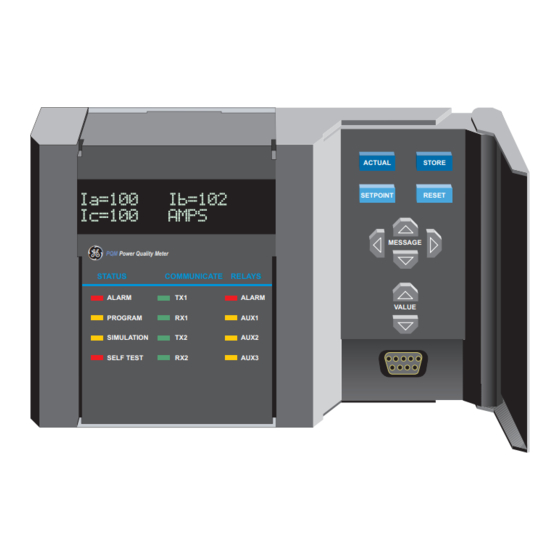
PQM
Power Quality Meter
STATUS
COMMUNICATE
ALARM
TX1
PROGRAM
RX1
SIMULATION
TX2
SELF TEST
RX2
PQM
Power Quality Meter™
INSTRUCTION MANUAL
Software Revision: 3.5x
Manual P/N: 1665-0003-CG
Manual Order Code: GEK-106296A
Copyright © 2001 GE Power Management
ACTUAL
SETPOINT
RELAYS
ALARM
AUX1
AUX2
AUX3
GE Power Management
STORE
RESET
MESSAGE
VALUE
823787A3.CDR
Manufactured under an
ISO9001 Registered system.
Advertisement
Table of Contents

Related Manuals for GE PQM Series


Summarization of Contents
PQM Power Quality Meter Instruction Manual
Software Revision
Indicates the software version of the PQM meter.
Manual Part Number
Manual P/N: 1665-0003-CG
Manual Order Code
Manual Order Code: GEK-106296A
Copyright Information
Copyright © 2001 GE Power Management
GE Power Management Contact
Contact details for GE Power Management including address, phone, and fax.
1 OVERVIEW
1.1 INTRODUCTION
Detailed explanation of the PQM meter's features and applications in power system monitoring.
1.2 STANDARD FEATURES
List of key monitoring, control, and communication capabilities of the PQM meter.
1.3 SPECIFICATIONS
Detailed technical specifications for current, voltage, sampling, analog I/O, and relays.
2 INSTALLATION
2.1 PHYSICAL
Physical dimensions and cutout requirements for panel or switchgear mounting.
2.2 ELECTRICAL
Wiring details for VT/Control Power, CT, and Signal Upper rows, including terminal assignments.
3 OPERATION
3.1 FRONT PANEL & DISPLAY
Description of the local operator interface, including keys, indicator LEDs, and RS232 port.
3.2 STATUS INDICATORS
Overview of status indicators for alarms, setpoint access, simulation, and PQM problems.
3.3 KEYPAD
Overview of the front panel keys used for setpoint entry and monitoring.
3.4 DEFAULT MESSAGES
How default messages are displayed when the PQM is unattended.
4 PROGRAMMING
4.1 INTRODUCTION
Options for entering system characteristics and alarm settings via front panel or computer.
4.2 S1 PQM SETUP
Configuration settings for the PQM itself, including preferences and communication ports.
4.3 S2 SYSTEM SETUP
Configuration of CT and VT wiring, primary ratings, and neutral sensing methods.
4.4 S3 OUTPUT RELAYS
Explanation of output relay operation modes (failsafe, non-failsafe) and activation (latched, unlatched).
4.5 S4 ALARMS/CONTROL
Configuration of alarms for phase/neutral under/overcurrent, undervoltage, and overvoltage conditions.
4.6 S5 TESTING
Manual testing of output relays and status indicators for correct operation.
5 MONITORING
5.1 ACTUAL VALUES VIEWING
How to display measured values, grouped by category (Metering, Status, Power Analysis, Product Info).
5.2 A1 METERING
Display of phase and neutral currents, average current, unbalance, and min/max values with timestamps.
5.3 A2 STATUS
List of all possible alarm conditions that can be triggered by the PQM.
5.4 A3 POWER ANALYSIS
Display of crest factor and transformer harmonic derating factor (THDF) for load current analysis.
5.5 A4 PRODUCT INFO
Display of product identification information, including software versions and order codes.
6 SOFTWARE
6.1 INTRODUCTION
Introduction to PQMPC software for programming, data analysis, and monitoring.
6.2 PQMPC INSTALLATION
Minimum system requirements and step-by-step guide for installing or upgrading PQMPC software.
6.3 PQMPC MENUS
Overview of PQMPC software menus for file operations, setpoint configuration, data viewing, and help.
6.4 UPGRADING FIRMWARE
Procedures for upgrading PQM firmware using downloaded files from the GE Power Management website.
6.5 USING PQMPC
Illustrates entering setpoints using PQMPC's interface, including drop-down menus and keypads.
6.6 POWER ANALYSIS
Capturing and displaying voltage and current waveforms for analysis of phase relationships and wiring issues.
7 MODBUS COMMUNICATIONS
7.1 OVERVIEW
Overview of Modbus RTU serial communication standard and its application with the PQM.
7.2 MODBUS FUNCTIONS
List of supported Modbus function codes for reading setpoints, actual values, and controlling operations.
7.3 MODBUS MEMORY MAP
Overview of how data is stored in the PQM memory as Setpoints and Actual Values.
8 DNP COMMUNICATIONS
8.1 DNP 3.0 PROTOCOL
Details on the PQM's support for Level 2 DNP V3.00 implementation, including frame sizes and retries.
8.1.2 IMPLEMENTATION TABLE
Lists all DNP objects recognized by the PQM, including function codes and qualifiers for requests and responses.
8.1.5 BINARY INPUT / BINARY INPUT CHANGE POINT LIST
Mapping of binary input indices to alarm conditions, switch states, and PQM features.
8.1.6 BINARY OUTPUT / CONTROL RELAY OUTPUT POINT LIST
List of points associated with binary outputs and control relay blocks, including reset and simulation functions.
8.1.7 POINT LIST FOR ANALOG INPUT/OUTPUT CHANGE
Table mapping Modbus registers to analog input/output points, including units, format, and event class.
8.1.8 POINT LIST FOR COUNTERS
List of points for binary counters (object 20) and frozen counters (object 21), including pulse inputs and energy values.
9 COMMISSIONING
9.1 COMMISSIONING
List of setpoints for S1 PQM Setup, including preferences, communication ports, DNP configuration, clock, and calculation parameters.
S2 SYSTEM SETUP
Configuration of CT and VT wiring, primary ratings, and neutral sensing methods.
S3 OUTPUT RELAYS
Configuration of output relays for alarm and auxiliary functions, detailing operation and activation.
S4 ALARMS/CONTROL
Configuration of alarms for current/voltage, total harmonic distortion, frequency, and power parameters.
S4 ALARMS/CONTROL continued
Configuration of alarms for power factor, demand, pulse input, time, and miscellaneous parameters.
S5 TESTING
Configuration of relay/LED tests and simulation of various inputs/outputs for testing purposes.
APPENDIX A
A.1 PQM APPLICATION NOTES
Application note detailing how the Event Recorder stores and defines events triggered by various situations.
A.1.2 INTERFACING USING HYPERTERMINAL
Guide for interfacing with the PQM using Hyperterminal for firmware upgrade when PQMPC is unavailable.
A.1.3 PHASORS IMPLEMENTATION
Explanation of how the PQM firmware calculates signal phasors using discrete Fourier series.
A.1.4 TRIGGERED TRACE MEMORY RESOLUTION
Details on how the PQM detects and records system disturbances using triggered trace memory.
A.1.5 PULSE OUTPUT APPLICATION
Application note on configuring PQM output relays as Pulse Initiators for energy quantity calculations.
A.1.6 DATA LOGGER IMPLEMENTATION
Implementation details for the data logger, including memory structure, modes, and parameter assignments.
ACCESSING THE DATA LOG INFORMATION
Methods for accessing and interpreting data log information via PQMPC or serial port.
A.1.7 READING LONG INTEGER VALUES FROM MEMORY MAP
Method for retrieving 32-bit (long integer) values from the PQM memory map using Modbus protocol.
A.1.8 PULSE INPUT APPLICATION
Application note on configuring PQM switch inputs as pulse counters for totalization.
A.1.9 PULSE TOTALIZER APPLICATION
Using PQM pulse inputs to totalize energy from multiple metering locations.
APPENDIX B
B.1 TABLES AND FIGURES
List of all tables included in the manual.
B.1.2 LIST OF FIGURES
List of all figures included in the manual.
APPENDIX C
C.1 PQM WARRANTY
GE Power Management relay warranty terms and conditions, including period and coverage.
Need help?
Do you have a question about the PQM Series and is the answer not in the manual?
Questions and answers