Table of Contents
Advertisement
Quick Links
Advertisement
Table of Contents

Related Manuals for Microtest 6377


Summarization of Contents
Safety and Precautions
General Safety Information
General safety requirements for measurement, control, and laboratory equipment.
AC Power Supply Guidelines
Information on AC power supply connections, cable requirements, and plug color codes.
Maintenance and Repair Safety
Warnings and precautions for adjustment, maintenance, and repair procedures.
Static Electricity Handling
Precautions for handling static-sensitive devices to prevent damage.
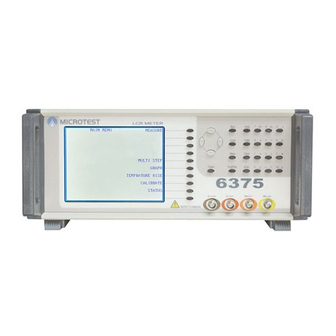
Introduction to the LCR Meter
Front Panel Overview
Identifies and describes the key components of the LCR meter's front panel.
Instrument Installation Procedures
AC Line Connections
Details on connecting the unit to the AC power supply, including voltage selection and fuse.
Measurement Connections
Information on various leads, fixtures, and adapters for making measurements.
Basic Instrument Operation
Rear Panel Layout
Description and layout of connectors and controls on the rear panel of the instrument.
Voltage Selector Setting
Instructions on setting the voltage selector switch for the correct AC power supply.
IEC Socket and Fuse Holder
Guidance on using the IEC socket and information about the fuse holder.
Rear Panel Control Connections
Table detailing labels, types, uses, and references for rear panel connections.
DC 5V Output and Trigger Input
Information on the DC 5V output, including external trigger input.
GPIB Communication Connector
Explanation of the General Purpose Interface Bus (GPIB) connector for remote operation.
GPIB Connector Pin Assignments
Pin assignment details for the GPIB connector.
Powering the Instrument On and Off
Instructions on how to power on/off the instrument and adjust display contrast.
Front Panel Controls and Interface
Front Panel Layout
Overview of the LCR meter's front panel layout and controls.
Soft Key Functions
Explanation of how soft keys are used to select modes and settings.
Navigation Key Usage
Description of navigation keys for parameter selection and adjustment.
Control Key Functions
Explanation of the function of various control keys on the front panel.
Data Entry Keypad
Overview of the data entry keypad for manual input of values and codes.
Keypad Special Codes
List of codes and their functions available via the data entry keypad.
Key Sequence Input Examples
Examples demonstrating how to input sequences using the data entry keypad.
Measurement and Calibration Procedures
Trimming for Measurement Accuracy
Explanation of the purpose and process of trimming to eliminate lead/fixture effects.
Performing O/C and S/C Trims
Step-by-step guide for performing Open Circuit (O/C) and Short Circuit (S/C) trims.
Available Trim Options
Description of different trim options available (All freq, Spot, <=10kHz, <=100kHz).
Measuring a Component
Instructions on how to measure a component using the LCR meter.
Capacitor Measurement Example
A step-by-step example of measuring capacitance and dissipation factor of a capacitor.
Measurement Mode Parameters
Detailed description of parameters selectable within the MEASUREMENT MODE.
Advanced Operation Modes
Terminal Connection Types
Explanation of using different terminal configurations for measurements.
Measuring Small Capacitors
Guidance on accurately measuring small value capacitors.
Measuring Small Inductors
Method for measuring very small inductors, emphasizing stable arrangements.
Iron-Cored and Ferrite Inductor Measurement
Considerations for measuring iron-cored and ferrite inductors, including magnetization effects.
Multi-Step Measurement Mode
Introduction to the MULTI STEP mode for sequential measurements.
Multi-Step Setup
Instructions for setting up multi-step measurement programs.
Multi-Step Execution
Procedure for running the configured multi-step measurement tests.
Multi-Step Trigger Modes
Explanation of auto and manual trigger modes for multi-step tests.
Instrument Status Page
How to access and view the instrument's status parameters.
Status Page Parameters
Details of parameters that can be altered on the STATUS page.
GPIB Interface Control
GPIB Control Introduction
Introduction to GPIB control and its capabilities.
Changing GPIB Address
Instructions on how to set or change the instrument's unique GPIB address.
GPIB Message Syntax
Explanation of the syntax rules for sending commands and messages via GPIB.
Hierarchical Command Structure
How SCPI uses a command tree structure for programming.
GPIB Data Output Formats
Details on how the instrument formats and outputs data in response to queries.
Status Reporting Mechanisms
Information on how the instrument reports its status and events.
Standard Event Status Register
Description of the bits within the standard event status register.
Common GPIB Commands
List and brief description of common commands applicable to instruments.
Standard Operation Status Commands
Commands related to reading instrument status conditions and events.
6375 Series Device-Specific Commands
Command Summary Overview
A summary table of all available commands with their descriptions and page references.
GPIB Example Programs
Illustrative QuickBasic programs demonstrating GPIB command usage.
Example 1: GPIB Identification
Example program for simple GPIB operation and identification check.
Example 2: Z+Angle Measurement
Example program for setting up and running a Z+Angle measurement.
Example 3: Querying Settings
Example program for querying current instrument settings.
Example 4: Multi-Step Measurements
Example program for multi-step measurements and results.
6375 Series Technical Specifications
Measurement Parameters
List of parameters that can be measured and displayed by the instrument.
Test Conditions
Conditions under which measurements are performed, including AC drive.
Drive Level and Measurement Speeds
Details on drive level settings and selectable measurement speeds.
Display Range and Modes of Operation
Instrument's display range capabilities and operating modes.
Measurement Accuracy Overview
General conditions and statements regarding the instrument's measurement accuracy.
Accuracy Charts and Formulas
Graphical charts and formulas for calculating measurement accuracy for various parameters.
General Instrument Specifications
General overview of instrument features, power, display, and remote control.
Environmental Operating Conditions
Conditions under which the equipment is intended to be operated.
Specific Environmental Parameters
Details on altitude, installation category, pollution degree, safety, and EMC.
Theory Reference for LCR Measurements
Abbreviations Glossary
Glossary of abbreviations used in the manual.
Relevant Measurement Formulas
Mathematical formulas and equations relevant to LCR theory.
Series and Parallel Conversions
Formulas for converting between series and parallel circuit parameters.
Polar Representation Derivations
Derivations and formulas for polar representation of impedance and admittance.
Maintenance, Support, and Service
Equipment Guarantee Details
Details of the equipment warranty and its limitations.
Instrument Maintenance Procedures
Procedures for cleaning and performing maintenance on the instrument.
Annual Safety Checks
Annual safety checks required for the equipment.
Support and Repair Services
Contact information and procedures for service and repairs.
Need help?
Do you have a question about the 6377 and is the answer not in the manual?
Questions and answers