Table of Contents
Advertisement
Quick Links
Advertisement
Table of Contents

Related Manuals for Microtest 6375


Summary of Contents for Microtest 6375
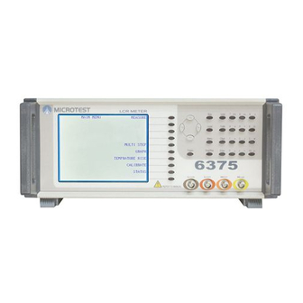
- Page 1 LCR METER 6375 / 6376 / 6377 / 6378/ 6379 User Manual...
-
Page 3: Table Of Contents
CONTENTS 1. SAFETY ..........................1–1 1.1 General ........................... 1–1 1.2 AC Power Supply ......................1–1 1.3 Adjustment, Maintenance and Repair ................1–2 1.4 Static Electricity ......................1–2 2. INTRODUCTION......................2–1 3. INSTALLATION ....................... 3–1 3.1 AC Line Connections ....................3–1 3.2 Measurement Connections ..................... - Page 4 6.1.5 Data Output ......................6–5 6.1.6 Status Reporting...................... 6–6 6.1.7 Common Commands ..................... 6–11 6.1.8 Standard Operation Status Commands ..............6–12 6.2 6375 Series Device-Specific Commands..............6–13 6.2.1 Command Summary ....................6–13 6.3 Example Programs ....................... 6–37 6.3.1 Example 1 ......................6–38 6.3.2 Example 2 ......................
- Page 5 8. THEORY REFERENCE ....................8–1 8.1 Abbreviations ......................... 8–1 8.2 Formulae ........................8–1 8.3 Series/Parallel Conversions ................... 8–2 8.4 Polar Derivations ......................8–2 9. MAINTENANCE, SUPPORT AND SERVICES ............9–1 9.1 Guarantee ........................9–1 9.2 Maintenance........................9–1 9.2.1 Cleaning ........................9–1 9.2.2 Safety Checks ......................
-
Page 7: Safety
Do not use the equipment if it is damaged. In such circumstances the equipment must be made inoperative and secured against any unintentional operation. Microtest and the associated sales organizations accept no responsibility for personal or material damage, nor for any consequential damage that results from irresponsible or unspecified operation or misuse of this equipment. -
Page 8: Adjustment, Maintenance And Repair
1–2 The user must also ensure that the protective ground lead would be the last to break should the cable be subject to excessive strain. If the plug is fused, a 3-amp fuse should be fitted. If the power cable electrical connection to the AC power plug is through screw terminals then, to ensure reliable connections, any solder tinning of the cable wires must be removed before fitting the plug. - Page 9 1–3 1) The work surface should be a conductive grounded mat. 2) Soldering irons must be grounded and tools must be in contact with a conductive surface to ground when not in use. 3) Any person handling static-sensitive parts must wear a wrist strap which provides a leaky path to ground, impedance not greater than 1M.
-
Page 11: Introduction
The 6375 Series LCR Meter provide 4-terminal (Kelvin) measurement of passive components over the frequency range 20Hz to 100kHz (6375) or 200kHz (6376) or 20Hz to 500KHz(6377) or 20Hz to 1MHz(6378) or 20Hz to 10MHz(6379) for AC measurements, the measurement drive level can be varied from 10mV to 2V rms. -
Page 13: Installation
The power switch is located on the left of the front panel. 3.2 Measurement Connections The 6375 Series can be used with any of the following Microtest leads, fixtures or adaptors. Kelvin Clip Leads (Fine Jaws), Part No. 1EVA40100 General purpose 4-terminal measuring leads for conventional components giving good accuracy except for measurement of very small capacitances or very small inductances where the use of the 4-terminal component fixture, part number 1EV1006, will give more accurate results. - Page 14 1100 Protection Unit, Part No. 1J1100 The standard protection built into the 6375 Series prevents damage to the instrument when charged capacitors are connected to the measurement terminals with energy levels up to 0.25J and a maximum voltage of 500V.
- Page 15 3–3 Figure 3-1 4-Terminal Measurement...
-
Page 17: Operation
DO NOT USE THIS EQUIPMENT IF IT IS DAMAGED. 4.1 The Rear Panel Figure 4-1 The 6375 Series Rear Panel 4.1.1 Voltage Selector The instrument can be operated from an AC power source of either 115V or 230V. Before applying AC power to the IEC socket, ensure that the voltage selector switch is set to the voltage of the local AC power supply. -
Page 18: Rear Panel Control Connections
4–2 4.1.3 Rear Panel Control Connections Label Type Reference GPIB Standard GPIB For remote operation. Sections 4.1.6 and 6 Duplicates action of front panel trigger DC 5V out Stereo phone jack Section 4.1.4 key. DC 5V output RS-232 9-way D-type (male) Reserved PRINTER Port 25-way D-type (female) -
Page 19: Switching The Instrument On
4–3 receptacle is recommended and should be compatible with the Amphenol and Cinch Series 57 or Amp Champ. 4.1.5.1 GPIB Connector Pin Assignment Description Description Data Line 1 Data Line 5 Data Line 2 Data Line 6 Data Line 3 Data Line 7 Data Line 4 Data Line 8... -
Page 20: The Front Panel
4–4 4.2 The Front Panel Figure 4-2 The6375 Series Front Panel 4.2.1 The Soft Keys The general protocol is that soft keys labelled with UPPER CASE letters select the labelled mode and soft keys labelled with lower case letters select settings within the current mode. The functions of the ten soft keys change according to the mode selected. -
Page 21: The Navigation Keys
4–5 Figure 4-3 The Soft Keys 4.2.2 The Navigation Keys Figure 4-4 The Navigation Keys When the set up details are showing on the screen (in some modes, there is a soft key which toggles between Hide Setup and Show Setup: this soft key can be seen in Figure 4-3), the left and right navigation keys, and , allow each parameter to be selected in turn. -
Page 22: The Data Entry Keypad
4–6 Pressing Local restores control to the front panel when the instrument is under GPIB control. Figure -The 6375 Series Main Menu Sngl/Rep toggles between Single shot mode and Repetitive mode. When Sngl/Rep is pressed the display briefly indicates the mode selected as shown in Figure 4-6 and Figure 4-7 below. - Page 23 4–7 The data-entry keypad is a multi-function key set permitting manual entry of data values, measurement units and control codes. The Units key must be used prior to keying a unit or multiplier. Where more than one unit is available on a key, e.g. D/Q or V/A, pressing the key will display the first unit, pressing the key again will display the second unit.
-
Page 24: Trimming
4–8 Key Sequence Examples (characters in Example 1: Supply the meter with a value of 27.39mH 1) Select the following settings in MEASUREMENT MODE: AC Meas, L, Q, Parallel, Show Scale, %. 2) Using the keys, highlight the nominal parameter (underneath the left-hand-side of the scale). -
Page 25: Performing An O/C Trim Or S/C Trim
Figure 4-11 Connections for S/C trimming of Kelvin clips 4.3.1 Performing an O/C Trim or S/C Trim.. Figure 4-12 6375 Series Calibrate Mode 1) Select CALIBRATE, either from the MAIN MENU, or from a mode which has CALIBRATE as an option (in which case pressing the RETURN soft key will return the meter to the original mode). -
Page 26: Measuring A Component
4–10 4.3.1.1 Trim Options. Figure 4-13 Trim Options All freq trims at a number of frequencies, including the frequency set when the trim was initiated. For most measurements made using standard test leads and fixtures this is the normal trim option to use. The other trim options are normally only used in exceptional circumstances, such as when a special test fixture fails O/C or S/C trim at certain frequencies outside of the component test parameters. -
Page 27: Example
4–11 Figure 4-14 Will be displayed. 3) Use the soft keys, shown in Figure 4-2 and Figure 4-3, to set the required measurement parameters: these are described in section 4.4.2 below. Do not exceed the limitations of the component to be measured. 4) Connect the component to be measured to the test leads or fixture. -
Page 28: Measurement Mode Parameters
4–12 AC Meas Parallel 5) Using the navigation keys, highlight and set each of the following parameters in turn. Use navigation keys to highlight a parameter and the navigation keys to alter the highlighted parameter setting. Settings may be altered one step at a time, or continuously by holding the navigation key down. - Page 29 4–13 The first measurement term. C L X B Z Y To select X, the Parallel/Series soft key must first be set to Series. To select B, the Parallel/Series soft key must first be set to Parallel. When either Z or Y are selected, the second measurement term is angle ( º ). The Q D R G and Parallel/Series soft keys are not appropriate and are therefore not shown.
- Page 30 4–14 Nom key. 2) Do not use the Save Nom function if the measured value is negative (e.g. an inductor measured above its self resonant frequency). Once the measurement parameters have been set, Hide Setup can be Show/Hide selected to clear them from the screen. The parameter settings are still valid Setup and will be used for component measurements.
- Page 31 Frequency altering the setting in pre-determined steps with the navigation keys, or by finer increments using the data entry keypad. The range is: 20Hz to 200KHz (6375) 20Hz to 500KHz (6376) 20Hz to 1MHz (6377) 20Hz to 5MHz...
-
Page 33: Advanced Operation
5–1 5. ADVANCED OPERATION This section will provide the user with a guide to: two-, three- and four-terminal connections measurement of very small capacitors measurement of very small inductors measurement of iron-cored and ferrite inductors 5.1 Two-, Three- and Four-Terminal Connections The meter has four front panel BNC sockets for screened cable connections to the device under test (DUT). -
Page 34: Measurement Of Iron-Cored And Ferrite Inductors
DUT inductance. A similar, stable fixture arrangement should be used for four-terminal measurements of surface- mount or leadless components: contact the Microtest Applications Department if this kind of fixture is required. The Q is always low, but self-capacitance is not normally a problem at the meter’s measurement frequencies. -
Page 35: Multi Step Mode
5–3 5.5 MULTI STEP MODE This mode allows measurement of components at a number of user-defined steps. Limits and parameters can be different for each defined step. MULTI STEP mode is divided into two areas: MULTI STEP – Set and MULTI STEP – Run. 5.5.1 MULTI STEP –... -
Page 36: Multi Step - Run
5–4 5.5.2 MULTI STEP – Run Before a multi-step test can be run it must be set up as described in section 5.5.1. Pressing the RUN soft key from MULTI STEP – Set mode enters MULTI STEP – Run mode. When the Start soft key or the Trigger key is pressed, the meter will measure the component step by step and the measurement values will be displayed. -
Page 37: The Status Page
5–5 5.6 The STATUS Page The status page is displayed by pressing the STATUS soft key from the MAIN MENU. Figure 5-3 The STATUS Page There are four parameters which may be altered from within the status page: Line frequency, Beep , External trigger delay and GPIB address. -
Page 39: General Purpose Interface Bus (Gpib)
6–1 6. GENERAL PURPOSE INTERFACE BUS (GPIB) 6.1 GPIB Control 6.1.1 Introduction The GPIB is a parallel port designed to be used for communication between instruments (listeners) and control devices (talkers) such as PCs fitted with a suitable interface card. The interface protocol is defined by the IEEE488.1 standard. -
Page 40: Message Syntax
6–2 The GPIB address is stored in non-volatile memory. 6.1.4 Message Syntax A GPIB message is made up of one or more commands. Commands can be separated into two groups, common commands and subsystem commands. The available common commands are defined by IEEE488.2 and are primarily concerned with the instrument’s GPIB configuration, e.g. - Page 41 6–3 1) Discrete data This includes words like ON, OFF and ABS. 2) Real Number A floating point number that can be in engineering format or a number with a multiplier suffix K (kilo-), M (mega-) or G (giga-). For example: FREQ 1000.0 FREQ 1E+3 FREQ 0.1E4...
- Page 42 6–4 The ‘:’ character is used as the path separator so the command string will be: :MEAS:FUNC:Z Note that the string starts with ‘:’. This tells the instrument to start from the ‘root’ path. Whenever a terminator is reached (line-feed and/or EOI) the path is reset to the root path, so each new GPIB command string must state the full path in order to work correctly, for example: To set a measurement frequency of 1kHz at a level of 1.0V, the following string can be used: :MEAS:FREQ 1k;LEV 1.0V <line-feed>...
-
Page 43: Data Output
6–5 Summary: The following are the rules for negotiating the command hierarchy On power-up or reset, the current path is set to the root. Message terminator, line-feed (ASCII 0Ah) or EOI, sets the current path to the root. ... -
Page 44: Status Reporting
6–6 Figure 6-4 GPIB RMU Structure 6.1.5.2 Multiple Items Some commands will generate an RMU containing more than one item of data (e.g. TRIG will generate a first and second result). In this case, each item of response data will be separated by a comma. - Page 45 6–7 Meaning True = ‘1’ A summary bit from Questionable Data. This bit is not used, so is always 0. This is a summary bit of error and instrument status messages. True if any new status information is available. Always 0. Always 0.
- Page 46 6–8 6.1.6.3 Standard Event Status Register The standard event status register (ESR) contains the 8 bits of the operation status report which is defined in IEEE 488.2. If one or more event status bit is set to ‘1’ and their enable bits are also ‘1’, bit 5 (called ESB) of the status register byte is set to ‘1’.
- Page 47 6–9 Standard Event Enable Register *ESR? Standard Event Enable Register Summary Message *ESE <NR1> *ESE? Event Summary Bit (ESB) (Bit 5 of Status Byte Register) Figure 6-7 Event Status Byte Register 6.1.6.4 Event Status Enable Register The event status enable register (ESE) is a mask determining the conditions in which the ESR will set bit 5 of the SBR.
- Page 48 6–10 :STATus:OPERation:CONdition? :STATus:OPERation:EVENt? STATus:OPERation:ENABle <NR1> Calibrating Settling Ranging Event register is updated on transition of condition register. Measuring Event register is masked by the enable register then ORed into a summary bit. Bit 7 of Status Byte Always Zero Figure 6-8 Standard Operation Status Group 6.1.6.5 Standard Operation Status Group The standard operation status group provides information about the state of the measurement systems in the instrument.
-
Page 49: Common Commands
Identification Query Returns the data identifying the instrument. (e.g. the data output will be: ‘Microtest,6375 Series,0,1.0’ where the first field is the manufacturer, then the model number, then a zero and the software revision number: here represented as Issue 1.0). -
Page 50: Standard Operation Status Commands
6–12 Command Name Description *OPC Operation Complete Command Sets the OPC bit of the ESR register. *OPC? Operation Complete Query Always returns 1 as instrument commands are always processed sequentially. *WAI Wait-to-continue Command has no effect as commands are processed sequentially. -
Page 51: 6375 Series Device-Specific Commands
6–13 6.2 6375 Series Device-Specific Commands The sub-system commands are grouped in different modes similar to the local operation. The recommended discipline to control the instrument under GPIB is to select the mode and the type of test first, then change the measurement conditions. Trying to change measurement conditions which are not in the present mode and type of test will be rejected and return an error flag. - Page 52 6–14 Command Summary Page :MEAS:NOMinal? Nominal query. 6-23 :MEAS:LIMIT <disc> Set percentage or absolute scale limits. 6-24 :MEAS:LIMIT? Limit type query. 6-24 :MEAS:HIgh-LIMit <real> Set scale high limit. 6-24 :MEAS:HIgh-LIMit? High limit query. 6-24 :MEAS:LOw-LIMit <real> Set scale low limit. 6-25 :MEAS:LOw-LIMit? Low limit query.
- Page 53 6–15 Command Summary Page :MULTI:NEW <filename> Create a file under a new name. 6-31 :MULTI:SAVE Save currently edited file. 6-32 MULTI:LOAD <filename> Load an existed file to run or edit. 6-32 :CAL Select calibrate mode / path. 6-43 :CAL:OC-TRIM <integer> Perform open circuit trimming.
- Page 54 6–16 MEASUREMENT MODE :MEAS Select measurement mode. Parameters: None. Response: None. :MEAS:TEST Select test sub-path within measurement mode. Parameters: None. Response: None. :MEAS:TEST:AC Select AC measurement. Parameters: None. Response: None. :MEAS:TEST:RDC Select Rdc measurement. Parameters: None. Response: None.
- Page 55 6–17 MEASUREMENT MODE :MEAS:TEST? Measurement test query. Parameters: None. Response: AC measurement type. Rdc measurement type. :MEAS:TRIGger Trigger a measurement using the current settings. Parameters: None. Response: For AC measurements the response will be the first and second measurements separated by a comma.
- Page 56 6–18 MEASUREMENT MODE :MEAS:LEVel <real> :MEAS:LEVel? Set drive level for currently selected test. Drive level query. Parameters: Parameters: The required level in Volt. The unit None. suffix ‘V’ is optional. Response: Example: MEAS:LEV 1.2V Returns the current test level in MEAS:LEV 200m engineering format.
- Page 57 6–19 MEASUREMENT MODE :MEAS:RANGE <disc> :MEAS:RANGE? Select the required measurement range Returns the current measurement range. condition for AC and RDC tests. Parameters: Parameters: None. The following parameters are valid: Response: AUTO Auto-ranging. Returns the measurement range as an HOLD Hold current range.
- Page 58 6–20 MEASUREMENT MODE :MEAS:FUNC Select function sub-path within measurement mode. Parameters: None. Response: None. :MEAS:FUNC:C, L, X, B, Z, Y, Q, D, R, G Select first or second AC measurement function. Selecting first measurement: :MEAS:FUNC:C Capacitance. :MEAS:FUNC:L Inductance. :MEAS:FUNC:X Reactance. :MEAS:FUNC:B Susceptance.
- Page 59 6–21 MEASUREMENT MODE :MEAS:FUNC:MAJOR? First AC function query. Parameters: None. Response: Returns the measurement type according to this table: Capacitance Inductance. Reactance. Susceptance. Impedance. Admittance. Example: 4 indicates that the first measurement is impedance (Z). :MEAS:FUNC:MINOR? Second AC function query. Parameters: None.
- Page 60 6–22 MEASUREMENT MODE :MEAS:SCALE <disc> :MEAS:SCALE? Show / Hide the scale bar. Returns the current status of the scale bar. Parameters: Parameters: The following parameters are valid: None. Show scale. Response: Hide scale. Returns scale setting according to this Example: :MEAS:SCALE OFF table: Scale hidden.
- Page 61 6–23 MEASUREMENT MODE :MEAS:LIMIT <disc> :MEAS:LIMIT? Set percentage or absolute scale limits. Limit type query. Parameters: Parameters: The following discrete parameters are None. valid: Response: Absolute limits. Returns the scale bar limits according PERC Percentage limits. to this table: Example: :MEAS:LIMIT PERC Absolute scale.
- Page 62 6–24 MEASUREMENT MODE :MEAS:LOw-LIMit <real> :MEAS:LOw-LIMit? Set scale low limit. Returns the current scale bar percentage low limit. Parameters: Parameters: The required low limit. No unit should be supplied: the nominal unit is used. None. Example: :MEAS:LO-LIM -5.0 Response: will set a low limit of -5.0% of The current low limit in engineering nominal.
- Page 63 6–25 MULTI-STEP MODE :MULTI Select multi-step mode / path. Parameters: None. Response: None. :MULTI:SET Switch to the multi-step set-up page. Parameters: None. Response: None. :MULTI:RUN Switch to the multi-step run page. Parameters: None. Response: None.
- Page 64 6–26 MULTI-STEP MODE :MULTI:TEST :MULTI:TEST? Select the step to edit. Return the number of the step that is currently being edited. Parameters: Parameters: The step number in the range 1 to 30. None. Example: :MULTI:TEST 1 will select the top frequency for editing Response: The frequency number in the range 1 to Response:...
- Page 65 6–27 MULTI-STEP MODE :MULTI:FREQuency <real> :MULTI:FREQuency? Set frequency for currently selected step. Frequency query of currently selected step. Parameters: Parameters: The required frequency in Hertz. The None. unit suffix ‘Hz’ is optional. Response: Example: MULTI:FREQ 1k Returns the current test frequency in MULTI:FREQ 1000 Hz engineering format.
- Page 66 6–28 MULTI-STEP MODE :MULTI:SPEED <disc> :MULTI:SPEED? Select the required measurement speed for Returns the test speed of currently selected step. currently selected step. Parameters: Parameters: None. Maximum speed. FAST Fast speed. Response: Medium speed. Returns the test speed as an integer according to the table: SLOW Slow speed.
- Page 67 6–29 MULTI-STEP MODE : MULTI:LOw-LIMit <real> : MULTI:LOw-LIMit? Set the lower test limit of the currently Returns the low limit value of the currently selected step. selected step. Parameters: Parameters: The required lower limit. None. Example: :MULTI:LO-LIM Response: 10.0 The low limit value in engineering will set a low limit to 10.
- Page 68 6–30 MULTI-STEP MODE :MULTI:TRIGger Starts a run of multi-step measurements. Parameters: None. Response: None. :MULTI:RES? Query the results of the multi-step test. Parameters: None Response: Each result is separated by a comma and the PASS/FAIL flag will prefix the result. PASS, FAIL (HI) FAIL (LO)
- Page 69 6–31 MULTI-STEP MODE MULTI:SAVE Store current multi-step data to currently selected file. Parameters: None. Response: None. MULTI:LOAD <filename> Load an existed file to run or edited. Parameters: A File name, 8 characters at most. Example: :MULTI:LOAD DEMO will load a file which name is DEMO. Response: None.
- Page 70 6–32 CALIBRATE MODE :CAL Select calibrate mode / path. Parameters: None. Response: None. :CAL:OC-TRIM <integer> Perform open circuit trimming. Parameters: The required trim type. Spot trim. Up to 10kHz. Up to 100kHz. All frequency. Example: :CAL:OC-TRIM 4 would perform an open circuit trim across the whole frequency range of the unit. Response: None.
- Page 71 6–33 CALIBRATE MODE :CAL:SC-TRIM <integer> Perform short circuit trimming. Parameters: The required trim type. Spot trim. Up to 10kHz. Up to 100kHz. All frequency. Example: :CAL:SC-TRIM 1 would perform a short circuit trim at the current frequency. Response: None. :CAL:RES? Returns the result of the most recent trim or calibration performed.
- Page 72 6–34 ROOT COMMANDS :TRIGger Trigger a measurement in the current mode. Parameters: None. Response: The measurement result depending on the mode. :TRIGger:DELAY <real> :TRIGger:DELAY? Set the trigger delay time for the external Query the external trigger delay time. trigger. Parameters: None.
- Page 73 6–35 ROOT COMMANDS :LOC-TRIG <disc> :LOC-TRIG? Select local trigger condition. When local Query the local trigger condition. trigger is ON the trigger button on the front Parameters: panel can be used to take a measurement, all other functions being under remote None.
- Page 74 6–36 ROOT COMMANDS :MODE? Query the currently selected operating mode. Parameters: None. Response: The current mode: Main menu. Measurement. Multi-step. Calibrate. Status. Example: 1 would indicate that Measurement Mode is selected. :DUMP-BMP Returns the display as a windows compatible bitmap. The data conforms to IEEE 488.2 or SCPI ‘Indefinite Length Arbitrary Block Response Data’.
-
Page 75: Example Programs
6–37 ROOT COMMANDS :BEEP <disc> :BEEP? Set the buzzer function. Query the buzzer condition. Parameters: Parameters: The required state: None. OFF Buzzer is disabled. Response: PASS Turns on the buzzer if test result The buzzer condition. is pass. FAIL Turns on the buzzer if test result PASS is fail. -
Page 76: Example 1
6–38 6.3.1 Example 1 ' ************************************************************** ' Program 1 : Simple GPIB operation check Version 1.0 ' Platform : QuickBasic 4.5 ' Description : ' This program will ask the instrument to identify itself. ' It assumes the instrument is called 'WK' in the National ' Instruments configuration. -
Page 77: Example 2
6–39 6.3.2 Example 2 ' ************************************************************** ' Program 2 : Simple Measurement Version 1.0 ' Platform : QuickBasic 4.5 ' Description : ' This program will set-up and run a single Z+Angle measurement ' on a component. ' This program assumes that the GPIB configuration is correct ' enough to be able to run example program 1 correctly. - Page 78 6–40 ' Program 3 : Querying the instrument state Version 1.0 ' Platform : QuickBasic 4.5 ' Description : ' This program will use queries to find out the current settings ' of the unit. ' This program assumes that the GPIB configuration is correct ' enough to be able to run example program 1 correctly.
-
Page 79: Example 4
6–41 CALL IBWRT(id%, Query$) ' Query the level CALL IBRD(id%, buf$) ' Read in the response. GPIBQuery$ = LEFT$(buf$, ibcnt% - 1) ' Remove trailing characters. END FUNCTION 6.3.4 Example 4 DECLARE FUNCTION GPIBQuery$ (id%, Query$) ' ************************************************************** ' Program 4 : Multi-step mode Version 1.0 ' Platform : QuickBasic 4.5 ' Description : ' This program sets up and runs a simple 4 frequency measurement... -
Page 81: Series Specification
7–1 7. 6375 SERIES SPECIFICATION Microtest reserves the right to change specification without notice 7.1 Measurement Parameters Any of the following parameters can be measured and displayed: DC Function Resistance (Rdc). AC Functions Capacitance (C), Inductance (L), Resistance (R), Conductance (G),... -
Page 82: Measurement Speeds
7–2 7.2.1.2 Drive Level (AC & DC Measurements) Open circuit voltage:10mV to 2V Short circuit current:100MA to 20mA Signal source impedance:100Ω nominal Resolution:10mV Accuracy:2%±5mV 7.3 Measurement Speeds Four selectable speeds for all measurement functions. Selecting slower measurement speed increases reading resolution and reduces measurement noise by averaging. est Frequency ≦100Hz ≦2kHz... -
Page 83: Display Range
7–3 7.4 Display Range 0.01mΩ to 1GΩ R, Z , X G, Y, B 0.001nS to 1kS 0.1nH to 100kH 0.001pF to 1F 0.00001 to 1000 0.01 to 1000 0.01mΩ to 100MΩ 7.5 Modes Of Operation 7.5.1 MEASUREMENT Selection of any measurement parameter and test condition. Single-level function-menu controlled by keypad and soft keys. - Page 84 7–4 Slow speed, 4-terminal measurement. The instrument must have warmed up for at least 30 minutes at a steady ambient temperature of between 18C and 28C. The instrument must have been trimmed with its measuring leads and fixture at the measurement frequency. Except on the highest and lowest hardware measurement ranges, the accuracy chart also apply to medium speed.
-
Page 85: Accuracy Chart
7–5 7.8 Accuracy Chart Accuracy chart define the measurement ranges available, at specified accuracies, over the available frequency band. All curves assume that Slow measurement speed is used, that the meter has been trimmed at the frequency and level used for measurements, factory calibration are valid and that the component under test is pure. -
Page 86: Z| Vs L, C Chart
7–6 7.8.2 |Z| vs L, C Chart... -
Page 87: D Accuracy
7–7 7.8.3 |Z|, |Y|, L, C, R, X, G, B and Rdc Accuracy For high impedance (>10kOhm) value: Ae[%] = ((A + 0.0000001*Zx) * Kv * Kt) For low impedance (<100Ohm) value Ae[%] = ((A + 0.1/Zx) * Kv * Kt) Where, A= Accuracy from accuracy chart Zx= Measured value of unknown component... - Page 88 7–8 Table A. Test voltage factor Level ≧ 1.250 ≧ 0.625 ≧ 0.313 ≧ 0.156 ≧ 0.078 ≧ 0.039 ≧ 0.02 ≧ 0.010 Table B Temperature factor Temperature(°C) 8-18 18-28 28-35...
-
Page 89: General
7–9 7.9 General 7.9.1 Power Supply Input Voltage 115V AC ±10% or 230V AC ±10% (selectable) Frequency 50/60Hz VA rating 150VA max Input fuse rating 115/230V operation: 3AT The input fuse is in the fuse holder drawer integral to the IEC input connector. 7.9.2 Display High contrast black and white LCD module 320 x 240 pixels with CPL back lighting. -
Page 90: Altitude
7–10 7.10.3 Altitude Up to 2000m. 7.10.4 Installation Category II in accordance with IEC664. 7.10.5 Pollution Degree 2 (mainly non-conductive). 7.10.6 Safety Complies with the requirements of EN61010-1. 7.10.7 EMC Complies with EN61326 for emissions and immunity. -
Page 91: Theory Reference
8–1 8. THEORY REFERENCE 8.1 Abbreviations Susceptance (= 1/X) Resistance Capacitance Reactance Dissipation factor (tan δ) Admittance (= 1/Z) Voltage Impedance ω 2π x frequency Conductance (= 1/R) Current Inductance Subscript s ( ) = series Quality (magnification) factor Subscript p ( ) = parallel 8.2 Formulae Z ... -
Page 92: Series/Parallel Conversions
8–2 (parallel values) (series values) Note value constant regardless series/par allel convention 8.3 Series/Parallel Conversions ... -
Page 93: Maintenance, Support And Services
9–1 9. MAINTENANCE, SUPPORT AND SERVICES 9.1 Guarantee The equipment supplied by is guaranteed against defective material and faulty manufacture for a period of twelve months from the date of dispatch. In the case of materials or components employed in the equipment but not manufactured by us, we allow the customer the period of any guarantee extended to us. -
Page 94: Support And Service
14F-6, No.79, Hsin Tai Wu Road, Sec. 1, Hsi-chih, Taipei 221, Taiwan, R.O.C. Tel: +886-2-2698-3877 Fax: +886-2-2698-4089 Email: sales@microtest.com.tw When returning the instrument please ensure adequate care is taken with packing and arrange insurance cover against transit damage or loss. If possible re-use the original packing box.
Need help?
Do you have a question about the 6375 and is the answer not in the manual?
Questions and answers