Table of Contents
Advertisement
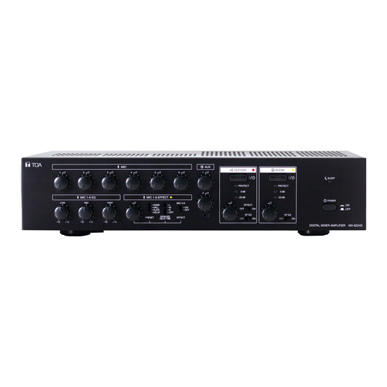
DIGITAL MIXER AMPLIFIER 2x240W
REMOTE CONTROLLER
Thank you for purchasing TOA's Digital Mixer Amplifier 2x240W and Remote Controller.
Please carefully follow the instructions in this manual to ensure long, trouble-free use of your equipment.
OPERATING INSTRUCTIONS
MX-6224D
RC-03
MX-6224D
133-02-00236-02
Advertisement
Table of Contents

Related Manuals for Toa RC-03


Summary of Contents for Toa RC-03
-
Page 1: Remote Controller
OPERATING INSTRUCTIONS DIGITAL MIXER AMPLIFIER 2x240W MX-6224D REMOTE CONTROLLER RC-03 MX-6224D Thank you for purchasing TOA's Digital Mixer Amplifier 2x240W and Remote Controller. Please carefully follow the instructions in this manual to ensure long, trouble-free use of your equipment. 133-02-00236-02... -
Page 2: Table Of Contents
5. HANDLING PRECAUTIONS ..............6 6. INSTALLATION PRECAUTIONS ............. 6 7. NOMENCLATURE AND FUNCTIONS ..........7 7.1. MX-6224D Digital Mixer Amplifier 2x240W ............7 7.2. RC-03 Remote Controller ..................10 8. CONNECTION EXAMPLE ................. 11 9. CONNECTIONS ....................12 9.1. Microphone Connections ..................13 9.2. -
Page 3: Safety Precautions
AC outlet and specified may result in fire or electric shock. contact your nearest TOA dealer. Make no further • Do not cut, kink, otherwise damage nor modify attempt to operate the unit in this condition as this the power supply cord. -
Page 4: General Description
2. GENERAL DESCRIPTION The MX-6224D Dual 240W Mixer Power Amplifier is designed for 2-zone Public address system suitable for small to middle sized mosques application. The optional RC-03 Remote Controller exclusively designed for use in conjunction with the MX-6224D permits ON/OFF control of speaker zones and sound effect function. -
Page 5: Recommended System
4. RECOMMENDED SYSTEM EM-410 DM-1300 Electret condenser Dynamic Microphones Microphone To AC mains MX-6224D CD Player DM-1300 BS-1030B Dynamic Microphones Box speaker x 4 TC-631M Horn speaker x 4 Ways of using MIC 2 − 4 and 5 − 6 are shown below as a guideline: MIC 2: Mount on a high microphone stand. -
Page 6: Handling Precautions
5. HANDLING PRECAUTIONS • The supplied power supply cord is designed to be used exclusively with the unit. Do not connect it to any other equipment. • Install the unit in locations where the temperature is between 0 and 40 °C and the moisture is between 35 and 80% (no dew condensation must be formed). -
Page 7: Nomenclature And Functions
7. NOMENCLATURE AND FUNCTIONS 7.1. MX-6224D Digital Mixer Amplifier 2x240W [Front] 15 16 17 18 19 22 23 24 1. Power switch the point where the red indicator (0 dB) begins to Turns on and off the main power. light. - Page 8 17. Effect Room size/Delay time selection switch Set this switch to the ON position to optimize Select the reverberation/delay time of effect from the output sound for the TOA TC-631M/651M "S" (Short time), "M" (Medium time), and "L" (Long speaker.
- Page 9 31. MIC 1 phantom switch 37. Effect bus output jacks When switched ON, phantom power is supplied 0 dB*, 600 Ω monaural, unbalanced, RCA pin to the MIC 1 input. Microphones connected to jacks (1 pair) the MIC 1 input depend on the switch setting as Connect to an external sound effector.
-
Page 10: Remote Controller
1. Control line connection ports 4. Outside zone switch Equipped with 2 RJ-45 ports. Turns on and off the outside zone output. Connect either of the 2 ports to the MX-6224D 5. Effect indicator amplifier. Maximum cable length is 200 m. -
Page 11: Connection Example
A-2030 Microphone Monitor speaker Mixer amplifier DM-1300 Dynamic Microphones RC-03 RC-03 RC-03 Remote controller To AC mains MX-6224D P-2240 Power amplifier DM-1300 BS-1030B Dynamic Box speaker x 4 Microphones P-2240 TC-631M Horn speaker x 4 Recorder Radio tuner or CD player... -
Page 12: Connections
(see p. 13) Remote Controller connections (see p. 18) Speaker connections (see p. 17) External Power Amp connections (see p. 17) External Auxiliary Equipment connections (see p. 15) External Effector connections (see p. 15) MX-6224D External Speaker Processor connections (see p. 16) -
Page 13: Microphone Connections
• Turning the phantom power switch ON causes a 24 V voltage to be applied to the phone plug's tip and ring. • When using a lavalier microphone, it is recommended that TOA's EM-410 Lavalier Microphone be used. Microphone sensitivity when phantom power is used or unused is as follows: When used: −50 dB*... - Page 14 9.1.3. MIC 2 – 6 connections Microphones equipped with either an XLR connector or a phone plug can be used with microphone inputs 2 – 6. • Balanced or unbalanced microphones can be connected to the phone jack. • Switching ON the phantom power switch supplies power to all MIC 2 – 6 XLR connectors. •...
-
Page 15: External Auxiliary Equipment Connections
9.2. External Auxiliary Equipment Connections 9.2.1. AUX 1 input jack connections Two input signals can be mixed within the unit. For stereo sound source wiring, connect to both RCA pin jacks. For monaural sound source wiring, connect to either jack. To external auxiliary equipment 9.2.2. -
Page 16: Monitor Speaker Connections
9.5. External Speaker Processor Connections TOA's DP-SP3 Digital Speaker Processor can be used as an external speaker processor without using the unit's internal speaker equalizer function (see p. 21). The external speaker processor can also be used for either the ROOM or OUTSIDE speakers. -
Page 17: Speaker Connections
100 V line speakers are connected to each speaker terminal and the total wattage is less than 240 W. • The unit can produce optimum sound quality conditions when the following TOA speakers are connected and the speaker equalizer function is used. (see p. 21.) -
Page 18: Remote Controller Connections
Do not connect any other equipment than the RC-03 Remote Controller CAUTION to the MX-6224D’s Remote controller connection port. If other equipment, such as a PC, hub or network device, is connected to that port, the connected equipment could be damaged. -
Page 19: Settings
10. SETTINGS After connection completion, perform settings while sound is actually being broadcasting (see p. 22). MX-6224D Microphone Equalizer Effector settings Speaker Equalizer settings settings (see below) (see below) (see p. 21) 10.1. Microphone Equalizer Settings The equalizer settings of MIC 1 – 6 can be adjusted to low, middle and high frequency bands. Rotating the Frequency Control knob of each band clockwise enhances the relevant band, while counterclockwise rotation weakens the band. - Page 20 10.2.1. Effector types and settings MX-6224D Step 1. Select the type of effect to be used with the Effect Preset Type Selection switch. Refer to the following table for the types of effects that can be selected: Effect Name Effect Description DOME Creates an effect of stone walls with semi-domed ceilings.
-
Page 21: Speaker Equalizer Settings
Effector disabled Effector enabled Outside zone output effect switch 10.3. Speaker Equalizer Settings The unit’s built-in speaker equalizer can be used to adjust the following TOA speakers for optimal sound quality: For ROOM zone: BS-1030B, BS-1030W For OUTSIDE zone: TC-631M. TC-651M To use this function, set the Equalizer switch ON for the desired zone(s). -
Page 22: Operations
11. OPERATIONS 11.1. Making Broadcasts 11.1.1. When using the MX-6224D amplifier alone for broadcasting 4, 6 1, 5 3, 7 MX-6224D 3, 7 Safety Measures to Prevent Abrupt Loud Sound Output Step 1. Ensure that the power switch is in the OFF position. - Page 23 11.1.2. When using the MX-6224D amplifier in conjunction with the RC-03 Remote Controller (1 – 3 units) for broadcasting 4, 6 1, 5 3, 7 MX-6224D 3, 7 RC-03 4, 6 Safety Measures to Prevent Abrupt Loud Sound Output Step 1. Ensure that the power switch is in the OFF position.
-
Page 24: Using Sleep Mode
After use, the amplifier can be placed in Sleep (standby) mode with no need of switching off its AC main power. Sleep mode can be enabled when both the outside and room outputs are OFF. 11.2.1. Setting the MX-6224D amplifier to Sleep mode Sleep indicator MX-6224D Step 1. -
Page 25: Switching The Ac Power Off
11.2.2. Setting the MX-6224D amplifier and the RC-03 Remote Controller (1 – 3 units) to Sleep mode MX-6224D Sleep indicator RC-03 Step 1. Fully rotate all volume controls counterclockwise. Step 2. Set all Zone switches for the OUTSIDE and ROOM outputs of the amplifier and Remote Controllers to OFF. -
Page 26: Rack Mounting
Note To improve ventilation, ensure that a perforated panel (panel with air openings) of 1-unit size or MX-6224D unit greater is mounted over and under the unit, as well as on the top and at the bottom of the rack. -
Page 27: Trouble Shooting
13. TROUBLE SHOOTING Symptom Possible Cause Remedy No sound output. When protection indicator is unlit AC power supply cord is not connected. Check connections. Microphone and other sound source are not connected. Speakers are not connected. Power switch is set to OFF. Set power switch to ON. -
Page 28: Block Diagram
14. BLOCK DIAGRAM... -
Page 29: Specifications
15. SPECIFICATIONS [MX-6224D] Power Source 220 V – 240 V AC, 50/60 Hz Power Output 240 W x 2 channels (100 V, 42 Ω, rated output) Power Consumption 100 W (according to IEC60065), 570 W (at rated output, both channels) -
Page 30: Dimensional Diagram
[RC-03] Power Source 5 V DC (supplied from MX-6224D) Consumption current 120 mA Maximum Terminal RJ-45 connector Controls 1 ROOM ON/OFF control switch 1 OUTSIDE ON/OFF control switch 1 Effect ON/OFF control switch Indicators CONNECTION indicator Output ON/OFF for ROOM and OUTSIDE... - Page 31 [RC-03] (MX-6224D ﺗﻴﺎﺭ ﻣﺒﺎﺷﺮ ٥ ﻓﻮﻟﻂ )ﻣﺰﻭﺩ ﻣﻦ ﻣﺼﺪﺭ ﺍﻟﺘﻴﺎﺭ ٠٢١ ﻣﻴﻠﻲ ﺃﻣﺒﻴﺮ ﻛﺤﺪ ﺃﻗﺼﻰ ﺍﺳﺘﻬﻼﻙ ﺍﻟﺘﻴﺎﺭ RJ-45 ﺍﻟﻤﻮﺻﻞ ﻃﺮﻑ ﺗﻮﺻﻴﻞ ( ﺍﻟﺨﺎﺹ ﺑﺎﻟﻨﻄﺎﻕ ﺍﻟﺪﺍﺧﻠﻲON/OFF) ١ ﻣﻔﺘﺎﺡ ﺍﻟﺘﺤﻜﻢ ﺑﺎﻟﺘﺸﻐﻴﻞ/ﺇﻏﻼﻕ ﻣﻔﺎﺗﻴﺢ ﺍﻟﺘﺤﻜﻢ ( ﺍﻟﺨﺎﺹ ﺑﺎﻟﻨﻄﺎﻕ ﺍﻟﺨﺎﺭﺟﻲON/OFF) ١ ﻣﻔﺘﺎﺡ ﺍﻟﺘﺤﻜﻢ ﺑﺎﻟﺘﺸﻐﻴﻞ/ﺇﻏﻼﻕ ( ﺍﻟﺨﺎﺹ ﺑﺎﻟﻤﺆﺛﺮﺍﺕON/OFF) ١ ﻣﻔﺘﺎﺡ ﺍﻟﺘﺤﻜﻢ ﺑﺎﻟﺘﺸﻐﻴﻞ/ﺇﻏﻼﻕ...
- Page 32 ٥١. ﺍﻟﻤﻮﺍﺻﻔﺎﺕ [MX-6224D] ﺗﻴﺎﺭ ﻣﺘﺮﺩﺩ ٠٢٢ ﻓﻮﻟﻂ - ٠٤٢ ﻓﻮﻟﻂ، ٠٥/٠٦ ﻫﺮﺗﺰ ﻣﺼﺪﺭ ﺍﻟﺘﻴﺎﺭ (٠٤٢ ﻭﺍﻁ × ٢ ﻗﻨﺎﺓ )٠٠١ ﻓﻮﻟﻂ، ٢٤ ﺃﻭﻡ، ﺧﺮﺝ ﺍﻟﻤﻌﺎﻳﺮ ﺧﺮﺝ ﺍﻟﺘﻴﺎﺭ (( ، ٠٧٥ ﻭﺍﻁ )ﻋﻨﺪ ﺍﻟﺨﺮﺝ ﺍﻟﻤﻘﺪﺭ، ﻛﻼ ﺍﻟﻘﻨﺎﺗﻴﻦIEC60065 ٠٠١ ﻭﺍﻁ )ﺍﺳﺘﻨﺎ ﺩ ً ﺇﻟﻰ...
- Page 33 ٤١. ﺭﺳﻢ ﺑﻴﺎﻧﻲ ﺗﺨﻄﻴﻄﻲ ٢٨...
- Page 34 ٣١. ﺗﺤﺮﻱ ﺍﻟﺨﻠﻞ ﻭﺇﺻﻼﺣﻪ ﺍﻟﻌﻼﺝ ﺍﻷﺳﺒﺎﺏ ﺍﻟﻤﺤﺘﻤﻠﺔ ﺍﻷﻋﺮﺍﺽ ﻋﻨﺪﻣﺎ ﻳﻜﻮﻥ ﻣﺆﺷﺮ ﺍﻟﺤﻤﺎﻳﺔ ﻏﻴﺮ ﻣﻀﺎء ﻻ ﻳﻮﺟﺪ ﺧﺮﺝ .ﻟﻠﺼﻮﺕ .ﺗﻔﻘﺪ ﺍﻟﺘﻮﺻﻴﻼﺕ .ﺳﻠﻚ ﺇﻣﺪﺍﺩ ﺍﻟﺘﻴﺎﺭ ﺍﻟﻤﺘﺮﺩﺩ ﻏﻴﺮ ﻣﻮﺻﻮﻝ .ﺍﻟﻤﻴﻜﺮﻭﻓﻮﻥ ﻭﻣﺼﺪﺭ ﺍﻟﺼﻮﺕ ﺍﻵﺧﺮ ﻏﻴﺮ ﻣﺘﺼﻠﺔ .ﺍﻟﺴﻤﺎﻋﺎﺕ ﻏﻴﺮ ﻣﺘﺼﻠﺔ .ON ﻗﻢ ﺑﻀﺒﻂ ﻣﻔﺘﺎﺡ ﺍﻟﺘﻴﺎﺭ ﻋﻠﻰ ﻭﺿﻊ ﺍﻟﺘﺸﻐﻴﻞ .OFF ﺗﻢ...
- Page 35 .ﻗﻢ ﺑﺘﺠﻬﻴﺰﻫﻢ ﻋﻠﻰ ﺃﻥ ﻳﻜﻮﻧﻮﺍ ﻣﻨﺎﺳﺒﻴﻦ ﻟﺤﺎﻣﻞ ﺍﻟﻌﺪﺓ ﻣﻼﺣﻈﺔ ﻣﻦ ﺃﺟﻞ ﺗﺤﺴﻴﻦ ﺍﻟﺘﻬﻮﻳﺔ، ﺍﺣﺮﺹ ﻋﻠﻰ ﺃﻥ ﺗﻜﻮﻥ ﺍﻟﻠﻮﺣﺔ ﺍﻟﻤﺨﺮﻣﺔ )ﺍﻟﻠﻮﺣﺔ ﺍﻟﺘﻲ ﺗﺤﺘﻮﻱ ﻋﻠﻰ ﻓﺘﺤﺎﺕ ﻟﻠﻬﻮﺍء( ﻣﻦ ﺣﺠﻢ ١-ﻭﺣﺪﺓ ﺃﻭ MX-6224D .ﺃﻋﻠﻰ ﻣﺜﺒﺘﺔ ﺃﻋﻠﻰ ﻭﺃﺳﻔﻞ ﺍﻟﻮﺣﺪﺓ، ﻛﺬﻟﻚ ﻓﻲ ﺃﻋﻠﻰ ﻭﺃﺳﻔﻞ ﺍﻟﺤﺎﻣﻞ ٢٦...
- Page 36 )١ - ٣ ﻭﺣﺪﺍﺕ( ﺇﻟﻰ ﻭﺿﻊ ﺍﻟﺴﻜﻮﻥRC-03 ﻭﺟﻬﺎﺯ ﺍﻟﺘﺤﻜﻢ ﻋﻦ ﺑﻌﺪMX-6224D ١١.٢.٢. ﺗﻬﻴﺌﺔ ﻣﻀﺨﻢ ﺍﻟﺼﻮﺕ MX-6224D .ﺍﻟﺨﻄﻮﺓ ١. ﻗﻢ ﺑﺘﺪﻭﻳﺮ ﻣﻔﺎﺗﻴﺢ ﺍﻟﺘﺤﻜﻢ ﺑﻤﺴﺘﻮﻯ ﺍﻟﺼﻮﺕ ﺑﺎﻟﻜﺎﻣﻞ ﺑﻌﻜﺲ ﺍﺗﺠﺎﻩ ﺣﺮﻛﺔ ﻋﻘﺎﺭﺏ ﺍﻟﺴﺎﻋﺔ .OFF ﺍﻟﺨﻄﻮﺓ ٢. ﻗﻢ ﺑﻀﺒﻂ ﺟﻤﻴﻊ ﻣﻔﺎﺗﻴﺢ ﺍﻟﻨﻄﺎﻕ ﻟﻤﺨﺎﺭﺝ ﺍﻟﺨﺎﺭﺟﻲ ﻭﺍﻟﺪﺍﺧﻠﻲ ﻟﻤﻀﺨﻢ ﺍﻟﺼﻮﺕ ﻭﺃﺟﻬﺰﺓ ﺍﻟﺘﺤﻜﻢ ﻋﻦ ﺑﻌﺪ ﻋﻠﻰ ﻭﺿﻊ ﺍﻹﻏﻼﻕ...
- Page 37 ﺑﻌﺪ ﺍﻻﺳﺘﺨﺪﺍﻡ، ﻳﻤﻜﻦ ﻭﺿﻊ ﻣﻀﺨﻢ ﺍﻟﺼﻮﺕ ﺑﻮﺿﻊ ﺍﻟﺴﻜﻮﻥ )ﺍﻻﺳﺘﻌﺪﺍﺩ( ﺩﻭﻥ ﺍﻟﺤﺎﺟﺔ ﻹﻏﻼﻕ ﺍﻟﺘﻴﺎﺭ ﺍﻟﻤﺘﺮﺩﺩ ﺍﻟﺮﺋﻴﺴﻲ. ﻣﻦ ﺍﻟﻤﻤﻜﻦ ﺃﻥ ﻳﺘﻢ ﺗﻤﻜﻴﻦ . ﻛﻞ ﻣﻦ ﺍﻟﻤﺨﺎﺭﺝ ﺍﻟﺨﺎﺭﺟﻲ ﻭﺍﻟﺪﺍﺧﻠﻲOFF ﻭﺿﻊ ﺍﻟﺴﻜﻮﻥ ﻋﻨﺪ ﺇﻏﻼﻕ ﻟﻮﺿﻊ ﺍﻟﺴﻜﻮﻥMX-6224D ١١.٢.١. ﺿﺒﻂ ﻣﻀﺨﻢ ﺍﻟﺼﻮﺕ MX-6224D .ﺍﻟﺨﻄﻮﺓ ١. ﻗﻢ ﺑﺘﺪﻭﻳﺮ ﻣﻔﺎﺗﻴﺢ ﺍﻟﺘﺤﻜﻢ ﺑﻤﺴﺘﻮﻯ ﺍﻟﺼﻮﺕ ﺑﺎﻟﻜﺎﻣﻞ ﺑﻌﻜﺲ ﺍﺗﺠﺎﻩ ﺣﺮﻛﺔ ﻋﻘﺎﺭﺏ ﺍﻟﺴﺎﻋﺔ...
- Page 38 )١ - ٣ ﻭﺣﺪﺍﺕ( ﻣﻦ ﺃﺟﻞ ﺇﺟﺮﺍء ﻋﻤﻠﻴﺔRC-03 ﺑﺎﻟﺘﺰﺍﻣﻦ ﻣﻊ ﺟﻬﺎﺯ ﺍﻟﺘﺤﻜﻢ ﻋﻦ ﺑﻌﺪMX-6224D ١١.١.٢. ﻋﻨﺪ ﺍﺳﺘﺨﺪﺍﻡ ﻣﻀﺨﻢ ﺍﻟﺼﻮﺕ ﺍﻟﺒﺚ ﺗﺪﺍﺑﻴﺮ ﺍﻟﺴﻼﻣﺔ ﻣﻦ ﺃﺟﻞ ﺗﻔﺎﺩﻱ ﺧﺮﺝ ﺍﻟﺼﻮﺕ ﺍﻟﻌﺎﻟﻲ ﺍﻟﺤﺎﺩ .OFF ﺍﻟﺨﻄﻮﺓ ١. ﺍﺣﺮﺹ ﻋﻠﻰ ﺃﻥ ﻳﻜﻮﻥ ﻣﻔﺘﺎﺡ ﺍﻟﺘﻴﺎﺭ ﻋﻠﻰ ﻭﺿﻊ ﺍﻹﻏﻼﻕ...
- Page 39 ١١. ﻋﻤﻠﻴﺎﺕ ﺍﻟﺘﺸﻐﻴﻞ ١١.١. ﺇﺟﺮﺍء ﻋﻤﻠﻴﺎﺕ ﺍﻟﺒﺚ ﺑﻤﻔﺮﺩﻩ ﻣﻦ ﺃﺟﻞ ﺇﺟﺮﺍء ﻋﻤﻠﻴﺔ ﺍﻟﺒﺚMX-6224D ١١.١.١. ﻋﻨﺪ ﺍﺳﺘﺨﺪﺍﻡ ﻣﻀﺨﻢ ﺍﻟﺼﻮﺕ ﺗﺪﺍﺑﻴﺮ ﺍﻟﺴﻼﻣﺔ ﻣﻦ ﺃﺟﻞ ﺗﻔﺎﺩﻱ ﺧﺮﺝ ﺍﻟﺼﻮﺕ ﺍﻟﻌﺎﻟﻲ ﺍﻟﺤﺎﺩ .OFF ﺍﻟﺨﻄﻮﺓ ١. ﺍﺣﺮﺹ ﻋﻠﻰ ﺃﻥ ﻳﻜﻮﻥ ﻣﻔﺘﺎﺡ ﺍﻟﺘﻴﺎﺭ ﻋﻠﻰ ﻭﺿﻊ ﺍﻹﻏﻼﻕ...
- Page 40 ﺗﻌﻄﻴﻞ ﺍﻟﻤﺆﺛﺮ ﺧﺮﺝ ﺍﻟﻨﻄﺎﻕ ﺧﺎﺭﺟﻲ ٠١.٣. ﺗﻬﻴﺌﺎﺕ ﻣﻌﺎﺩﻝ ﺍﻟﺴﻤﺎﻋﺔ : ﺍﻟﺘﺎﻟﻴﺔ ﻟﻠﺤﺼﻮﻝ ﻋﻠﻰ ﺟﻮﺩﺓ ﺻﻮﺕ ﻣﺜﻠﻰTOA ﻳﻤﻜﻦ ﺍﺳﺘﺨﺪﺍﻡ ﻣﻌﺎﺩﻝ ﺍﻟﺴﻤﺎﻋﺔ ﺍﻟﻤﺪﻣﺞ ﺑﺎﻟﻮﺣﺪﺓ ﻟﻀﺒﻂ ﺳﻤﺎﻋﺎﺕ BS-1030W ،BS-1030B :ﻟﻠﻨﻄﺎﻕ ﺩﺍﺧﻠﻲ TC-651M .TC-631M :ﻟﻠﻨﻄﺎﻕ ﺧﺎﺭﺟﻲ . ﻟﻠﺤﺼﻮﻝ ﻋﻠﻰ ﺍﻟﻨﻄﺎﻕ )ﺍﻟﻨﻄﺎﻗﺎﺕ( ﺍﻟﻤﺮﻏﻮﺑﺔON ﻻﺳﺘﺨﺪﺍﻡ ﻫﺬﻩ ﺍﻟﻮﻇﻴﻔﺔ، ﻗﻢ ﺑﻀﺒﻂ ﻣﻔﺘﺎﺡ ﺍﻟﻤﻌﺎﺩﻝ ﻋﻠﻰ ﻭﺿﻊ ﺍﻟﺘﺸﻐﻴﻞ...
- Page 41 ٠١.٢.١. ﺃﻧﻮﺍﻉ ﺍﻟﻤﺆﺛﺮﺍﺕ ﻭﺇﻋﺪﺍﺩﺍﺗﻬﺎ .ﺍﻟﺨﻄﻮﺓ ١. ﻗﻢ ﺑﺎﺧﺘﻴﺎﺭ ﻧﻮﻉ ﺍﻟﻤﺆﺛﺮﺍﺕ ﺍﻟﺘﻲ ﺳﻴﺘﻢ ﺍﺳﺘﺨﺪﺍﻣﻬﺎ ﻣﻊ ﻣﻔﺘﺎﺡ ﺍﺧﺘﻴﺎﺭ ﻧﻮﻉ ﺍﻟﻤﺆﺛﺮﺍﺕ ﺍﻟﻤﻀﺒﻮﻃﺔ ﻣﺴﺒﻘ ً ﺎ :ﻗﻢ ﺑﺎﻟﺮﺟﻮﻉ ﺇﻟﻰ ﺍﻟﺠﺪﻭﻝ ﺍﻟﺘﺎﻟﻲ ﻟﻤﻌﺮﻓﺔ ﺃﻧﻮﺍﻉ ﺍﻟﺘﺄﺛﻴﺮﺍﺕ ﺍﻟﺘﻲ ﻳﻤﻜﻦ ﺍﺧﺘﻴﺎﺭﻫﺎ ﻭﺻﻒ ﺍﻟﻤﺆﺛﺮﺍﺕ ﺍﺳﻢ ﺍﻟﻤﺆﺛﺮﺍﺕ .ﻳﻘﻮﻡ ﺑﺈﺣﺪﺍﺙ ﺗﺄﺛﻴﺮ ﻟﺠﺪﺭﺍﻥ ﻣﻦ ﺍﻟﺤﺠﺮ ﺑﺴﻘﻒ ﺷﺒﻪ ﻣﻘ ﺒ ّﺐ ﻗﺒﺔ...
- Page 42 ٠١. ﺍﻟﺘﻬﻴﺌﺎﺕ .(٢٢ .ﺑﻌﺪ ﺍﻛﺘﻤﺎﻝ ﺍﻟﺘﻮﺻﻴﻞ، ﻗﻢ ﺑﺈﺟﺮﺍء ﺍﻟﺘﻬﻴﺌﺎﺕ ﺑﻴﻨﻤﺎ ﻳﺘﻢ ﺑﺚ ﺍﻟﺼﻮﺕ ﺣﺎﻟ ﻴ ًﺎ )ﺍﻧﻈﺮ ﺹ MX-6224D ﺗﻬﻴﺌﺎﺕ ﻣﻌﺎﺩﻝ ﺍﻟﻤﻴﻜﺮﻭﻓﻮﻥ ﺗﻬﻴﺌﺎﺕ ﺍﻟﻤﺆﺛﺮ ﺗﻬﻴﺌﺎﺕ ﻣﻌﺎﺩﻝ ﺍﻟﺴﻤﺎﻋﺔ ()ﺍﻧﻈﺮ ﺃﺩﻧﺎﻩ ()ﺍﻧﻈﺮ ﺃﺩﻧﺎﻩ (٢١ .)ﺍﻧﻈﺮ ﺹ ٠١.١. ﺗﻬﻴﺌﺎﺕ ﻣﻌﺎﺩﻝ ﺍﻟﻤﻴﻜﺮﻭﻓﻮﻥ ﻳﻤﻜﻦ ﺿﺒﻂ ﺗﻬﻴﺌﺎﺕ ﺍﻟﻤﻌﺎﺩﻝ ﺍﻟﺨﺎﺹ ﺑﺎﻟﻤﻴﻜﺮﻭﻓﻮﻥ ١ - ٦ ﺇﻟﻰ ﻛﻞ ﻣﻦ ﻧﻄﺎﻗﺎﺕ ﺍﻟﺘﺮﺩﺩ ﻣﻨﺨﻔﺾ ﻭﻣﺘﻮﺳﻂ ﻭﻋﺎﻟﻲ. ﻳﻌﺰﺯ ﺇﺩﺍﺭﺓ ﻣﻘﺒﺾ ﺍﻟﺘﺤﻜﻢ ﺑﺎﻟﺘﺮﺩﺩ...
- Page 43 RC-03 ٩.٨. ﺗﻮﺻﻴﻼﺕ ﺟﻬﺎﺯ ﺍﻟﺘﺤﻜﻢ ﻋﻦ ﺑﻌﺪ .MX-6224D ﺑﻤﻨﻔﺬ ﺗﻮﺻﻴﻞ ﻭﺣﺪﺓ ﺍﻟﺘﺤﻜﻢ ﻋﻦ ﺑﻌﺪRC-03 ﻻ ﺗﻌﻤﺪ ﺇﻟﻰ ﺗﻮﺻﻴﻞ ﺃﻱ ﺟﻬﺎﺯ ﺁﺧﺮ ﻏﻴﺮ ﻭﺣﺪﺓ ﺍﻟﺘﺤﻜﻢ ﻋﻦ ﺑﻌﺪ ﺗﻨﺒﻴﻪ ﺇﺫﺍ ﺗﻢ ﺗﻮﺻﻴﻞ ﺟﻬﺎﺯ ﺁﺧﺮ، ﻛﺠﻬﺎﺯ ﺍﻟﻜﻤﺒﻴﻮﺗﺮ ﺍﻟﺸﺨﺼﻲ ﺃﻭ ﻣﺠﻤﻊ ﺍﻟﻮﺻﻼﺕ ﺃﻭ ﺟﻬﺎﺯ ﺍﻟﺸﺒﻜﺔ ﻣﺜﻼ ً ، ﺑﺎﻟﻤﻨﻔﺬ، ﻓﻤﻦ ﺍﻟﻤﻤﻜﻦ...
- Page 44 • .ﻋﺎﻟﻴﺔ ﻓﻲ ﻛﻞ ﻃﺮﻑ ﺗﻮﺻﻴﻞ ﺧﺎﺹ ﺑﺎﻟﺴﻤﺎﻋﺔ ﻭﻳﻜﻮﻥ ﻣﺠﻤﻮﻉ ﺍﻟﻮﺍﻃﻴﺔ ﺃﻗﻞ ﻣﻦ ٠٤٢ ﻭﺍﻁ (.٢١ . ﺍﻟﺘﺎﻟﻴﺔ ﻭﻋﻨﺪ ﺍﺳﺘﺨﺪﺍﻡ ﻭﻇﻴﻔﺔ ﺍﻟﻤﻌﺎﺩﻝ. )ﺍﻧﻈﺮ ﺹTOA ﻳﻤﻜﻦ ﺃﻥ ﺗﻨﺘﺞ ﺍﻟﻮﺣﺪﺓ ﺃﻭﺿﺎﻉ ﻣﺜﻠﻰ ﻟﺠﻮﺩﺓ ﺍﻟﺼﻮﺕ ﻋﻨﺪﻣﺎ ﻳﺘﻢ ﺗﻮﺻﻴﻞ ﺳﻤﺎﻋﺎﺕ • BS-1030W ،BS-1030B :ﻟﻠﻨﻄﺎﻕ ﺩﺍﺧﻠﻲ...
- Page 45 • ٩.٥. ﺗﻮﺻﻴﻼﺕ ﻣﻌﺎﻟﺞ ﺍﻟﺴﻤﺎﻋﺔ ﺍﻟﺨﺎﺭﺟﻴﺔ .(٢١ . ﻛﻤﻌﺎﻟﺞ ﺳﻤﺎﻋﺔ ﺧﺎﺭﺟﻲ ﺩﻭﻥ ﺍﺳﺘﺨﺪﺍﻡ ﻭﻇﻴﻔﺔ ﻣﻌﺎﺩﻝ ﺍﻟﺴﻤﺎﻋﺔ ﺍﻟﺪﺍﺧﻠﻴﺔ )ﺍﻧﻈﺮ ﺹTOA ﻣﻦDP-SP3 ﻳﻤﻜﻦ ﺍﺳﺘﺨﺪﺍﻡ ﻣﻌﺎﻟﺞ ﺍﻟﺴﻤﺎﻋﺔ ﺍﻟﺮﻗﻤﻴﺔ .ﻛﻤﺎ ﻳﻤﻜﻦ ﺍﺳﺘﺨﺪﺍﻡ ﻣﻌﺎﻟﺞ ﺍﻟﺴﻤﺎﻋﺔ ﺍﻟﺨﺎﺭﺟﻴﺔ ﻷﻱ ﻣﻦ ﺍﻟﺴﻤﺎﻋﺎﺕ ﺍﻟﺪﺍﺧﻠﻴﺔ ﺃﻭ ﺍﻟﺨﺎﺭﺟﻴﺔ .DP-SP3 ، ﺭﺍﺟﻊ ﺩﻟﻴﻞ ﺍﻟﺘﻌﻠﻴﻤﺎﺕ ﺍﻟﻤﺮﻓﻖ ﻣﻊDP-SP3 ﻟﻠﺤﺼﻮﻝ ﻋﻠﻰ ﺍﻟﻤﺰﻳﺪ ﻣﻦ ﺍﻟﻤﻌﻠﻮﻣﺎﺕ ﺍﻟﻤﺘﻌﻠﻘﺔ ﺑﺎﺳﺘﺨﺪﺍﻡ ﺍﻟﻤﻌﺎﻟﺞ...
- Page 46 ٩.٢. ﺍﻟﺘﻮﺻﻴﻼﺕ ﺍﻟﺨﺎﺻﺔ ﺑﺎﻷﺟﻬﺰﺓ ﺍﻹﺿﺎﻓﻴﺔ ﺍﻟﺨﺎﺭﺟﻴﺔ ١ ٩.٢.١. ﺗﻮﺻﻴﻼﺕ ﻗﺎﺑﺲ ﺩﺧﻞ ﺇﺿﺎﻓﻲ ﻳﻤﻜﻦ ﻣﺰﺝ ﺇﺷﺎﺭﺗﻴﻦ ﻟﻠﺪﺧﻞ ﻓﻲ ﺍﻟﻮﺣﺪﺓ. ﻟﻠﻘﻴﺎﻡ ﺑﻌﻤﻞ ﺗﻤﺪﻳﺪﺍﺕ ﻟﻸﺳﻼﻙ ﺍﻟﺨﺎﺻﺔ ﻓﻲ ﻣﺼﺪﺭ ﺻﻮﺕ ﺍﻟﺴﺘﻴﺮﻳﻮ، ﻗﻢ ﺑﺘﻮﺻﻴﻞ ﻛﻼ ً ﻣﻦ ﺍﻟﻘﺎﺑﺴﻴﻦ . ﻟﺘﻤﺪﻳﺪﺍﺕ ﺍﻷﺳﻼﻙ ﺍﻟﺨﺎﺻﺔ ﻓﻲ ﻣﺼﺪﺭ ﺍﻟﺼﻮﺕRCA ﺍﻟﻤﺤﻮﺭﻳﻴﻦ .ﺍﻷﺣﺎﺩﻱ،...
- Page 47 ٦ - ٢ ٩.١.٣. ﺗﻮﺻﻴﻼﺕ ﺍﻟﻤﻴﻜﺮﻭﻓﻮﻥ .٦ - ٢ ﺃﻭ ﺑﻤﻘﺒﺲ ﻫﺎﺗﻒ ﻓﻲ ﻣﺪﺍﺧﻞ ﺍﻟﻤﻴﻜﺮﻭﻓﻮﻥXLR ﻳﻤﻜﻦ ﺍﺳﺘﺨﺪﺍﻡ ﺍﻟﻤﻴﻜﺮﻭﻓﻮﻧﺎﺕ ﺍﻟﻤﺠﻬﺰﺓ ﺇﻣﺎ ﺑﻤﻮﺻﻞ .ﻳﻤﻜﻦ ﺗﻮﺻﻴﻞ ﺍﻟﻤﻴﻜﺮﻭﻓﻮﻧﺎﺕ ﺍﻟﻤﺘﻮﺍﺯﻧﺔ ﺃﻭ ﻏﻴﺮ ﺍﻟﻤﺘﻮﺍﺯﻧﺔ ﻓﻲ ﻗﺎﺑﺲ ﺍﻟﻬﺎﺗﻒ • . ﺍﻟﺨﺎﺻﺔ ﺑﺎﻟﻤﻴﻜﺮﻭﻓﻮﻥ ٢ - ٦ ﺑﺎﻟﺘﻴﺎﺭXLR ﻳﻌﻤﻞ ﻋﻠﻰ ﺗﺰﻭﻳﺪ ﺟﻤﻴﻊ ﻣﻮﺻﻼﺕON ﺇﺩﺍﺭﺓ ﻣﻔﺘﺎﺡ ﺍﻟﺘﻴﺎﺭ ﻓﺎﻧﺘﻮﻡ ﺇﻟﻰ ﻭﺿﻊ ﺍﻟﺘﺸﻐﻴﻞ •...
- Page 48 . ﻳﺘﺴﺒﺐ ﻓﻲ ﺗﻄﺒﻴﻖ ﺟﻬﺪ ﺑﻘﺪﺭﺓ ٤٢ ﻓﻮﻟﻂ ﻟﻠﻤﺤﻮﺭ ﻭﺣﻠﻘﺔ ﻣﻘﺒﺲ ﺍﻟﻬﺎﺗﻒON ﺇﺩﺍﺭﺓ ﻣﻔﺘﺎﺡ ﺍﻟﺘﻴﺎﺭ ﻓﺎﻧﺘﻮﻡ ﺇﻟﻰ ﻭﺿﻊ ﺍﻟﺘﺸﻐﻴﻞ • .EM-410 ﻣﻦ ﺍﻟﻤﻮﺩﻳﻞTOA ﻋﻨﺪ ﺍﺳﺘﺨﺪﺍﻡ ﺍﻟﻤﻴﻜﺮﻭﻓﻮﻥ ﺍﻟﻤﺜﺒﺖ ﻋﻠﻰ ﺍﻟﺼﺪﺭ، ﻳﻮﺻﻰ ﺑﺎﺳﺘﻌﻤﺎﻝ ﺍﻟﻤﻴﻜﺮﻭﻓﻮﻥ ﺍﻟﻤﺜﺒﺖ ﻋﻠﻰ ﺍﻟﺼﺪﺭ • :ﺗﻜﻮﻥ ﺣﺴﺎﺳﻴﺔ ﺍﻟﻤﻴﻜﺮﻭﻓﻮﻥ ﻋﻨﺪ ﺍﺳﺘﺨﺪﺍﻡ ﺃﻭ ﻋﺪﻡ ﺍﺳﺘﺨﺪﺍﻡ ﺍﻟﺘﻴﺎﺭ ﻓﺎﻧﺘﻮﻡ ﻋﻠﻰ ﺍﻟﻨﺤﻮ ﺍﻟﺘﺎﻟﻲ...
- Page 49 ﻋﻦ ﺑﻌﺪ (١٨ .)ﺍﻧﻈﺮ ﺹ ﺗﻮﺻﻴﻼﺕ ﺍﻟﺴﻤﺎﻋﺔ (١٧ .)ﺍﻧﻈﺮ ﺹ ﺗﻮﺻﻴﻼﺕ ﻃﺎﻗﺔ ﻣﻀﺨﻢ (١٧ .ﺍﻟﺼﻮﺕ ﺍﻟﺨﺎﺭﺟﻲ )ﺍﻧﻈﺮ ﺹ ﺗﻮﺻﻴﻼﺕ ﺃﺟﻬﺰﺓ ﺇﺿﺎﻓﻴﺔ ﺧﺎﺭﺟﻴﺔ (١٥ .)ﺍﻧﻈﺮ ﺹ ﺗﻮﺻﻴﻼﺕ ﺍﻟﻤﺆﺛﺮ ﺍﻟﺨﺎﺭﺟﻴﺔ (١٥ .)ﺍﻧﻈﺮ ﺹ MX-6224D (١٦ .ﺗﻮﺻﻴﻼﺕ ﻣﻌﺎﻟﺞ ﺍﻟﺴﻤﺎﻋﺔ ﺍﻟﺨﺎﺭﺟﻲ )ﺍﻧﻈﺮ ﺹ ١٢...
- Page 50 ٨. ﻣﺜﺎﻝ ﻋﻠﻰ ﺍﻟﺘﻮﺻﻴﻞ DM-1300 EM-410 F-1300B A-2030 DM-1300 RC-03 RC-03 RC-03 MX-6224D P-2240 DM-1300 BS-1030B P-2240 TC-631M []ﺍﻟﺘﻮﺻﻴﻞ ﻋﻨﺪ ﺍﺳﺘﺨﺪﺍﻡ ﺟﻬﺎﺯ ﻣﻌﺎﻟﺠﺔ ﺍﻹﺷﺎﺭﺓ MX-6224D DP-SP3 ١١...
- Page 51 ٨. ﻣﻔﺘﺎﺡ ﺍﻟﻨﻄﺎﻕ ﺍﻟﺪﺍﺧﻠﻲ ﻳﻀﻲء ﺑﺎﻟﻠﻮﻥ ﺍﻷﺧﻀﺮ ﻋﻨﺪﻣﺎ ﻳﺘﻢ ﺗﻮﺻﻴﻞ ﺟﻬﺎﺯ ﺍﻟﺘﺤﻜﻢ ﻋﻦ ﺑﻌﺪ ﻓﻲ .ﻳﻘﻮﻡ ﺑﺘﺸﻐﻴﻞ ﻭﺇﻳﻘﺎﻑ ﺧﺮﺝ ﺍﻟﻨﻄﺎﻕ ﺍﻟﺪﺍﺧﻠﻲ MX-6224D ﺑﻴﻨﻤﺎ ﻳﻜﻮﻥ ﻣﻔﺘﺎﺡ ﺍﻟﺘﻴﺎﺭ ﺍﻟﺨﺎﺹ ﻓﻲMX-6224D .ON ﻋﻠﻰ ﻭﺿﻊ ﺍﻟﺘﺸﻐﻴﻞ ٣. ﻣﺆﺷﺮ ﺍﻟﻨﻄﺎﻕ ﺍﻟﺨﺎﺭﺟﻲ .ﻳﻀﻲء ﺑﺎﻟﻠﻮﻥ ﺍﻷﺣﻤﺮ ﻋﻨﺪ ﺧﺮﻭﺝ ﺍﻟﺼﻮﺕ ﺇﻟﻰ ﺍﻟﻨﻄﺎﻕ ﺍﻟﺨﺎﺭﺟﻲ...
- Page 52 ٧٣. ﻗﺎﺑﺴﺎﺕ ﺧﺮﺝ ﻧﺎﻗﻞ ﺍﻟﻤﺆﺛﺮﺍﺕ ١ ١٣. ﺍﻟﻤﻔﺘﺎﺡ ﻓﺎﻧﺘﻮﻡ ﻟﻠﻤﻴﻜﺮﻭﻓﻮﻥ ٠ ﺩﻳﺴﻴﺒﻞ*، ٠٠٦ ﺃﻭﻡ ﺃﺣﺎﺩﻱ، ﻏﻴﺮ ﻣﺘﻮﺍﺯﻥ، ﻗﺎﺑﺴﺎﺕ ﻣﺤﻮﺭﻳﺔ ، ﻳﺘﻢ ﺗﺰﻭﻳﺪ ﺍﻟﺘﻴﺎﺭ ﻓﺎﻧﺘﻮﻡ ﻟﺪﺧﻞON ﻋﻨﺪ ﺗﺪﻭﻳﺮﻩ ﻟﻮﺿﻊ ﺍﻟﺘﺸﻐﻴﻞ ( )ﺯﻭﺝ ﻭﺍﺣﺪRCA ﺍﻟﻤﻴﻜﺮﻭﻓﻮﻥ ١. ﺗﻌﺘﻤﺪ ﺍﻟﻤﻴﻜﺮﻭﻓﻮﻧﺎﺕ ﺍﻟﻤﺘﺼﻠﺔ ﻓﻲ ﺩﺧﻞ ﺍﻟﻤﻴﻜﺮﻭﻓﻮﻥ .ﺗﻘﻮﻡ...
- Page 53 (٢٢. ﻣﻔﺘﺎﺡ ﺍﻟﻤﻌﺎﺩﻝ )ﺳﻤﺎﻋﺔ ﺑﺸﻜﻞ ﺑﻮﻕ ﻟﺘﺤﺴﻴﻦ ﺧﺮﺝ ﺍﻟﺼﻮﺕON ﻗﻢ ﺑﺘﻬﻴﺌﺔ ﺍﻟﻤﻔﺘﺎﺡ ﻋﻠﻰ ﻭﺿﻊ ﺍﻟﺘﺸﻐﻴﻞ ٧١. ﻣﻔﺘﺎﺡ ﺍﺧﺘﻴﺎﺭ ﻣﺆﺛﺮﺍﺕ ﺍﻟﺤﺠﻢ ﺍﻟﺪﺍﺧﻠﻲ/ﺗﺄﺧﻴﺮ ﺯﻣﻨﻲ .TOA TC-631M/651M ﻟﺴﻤﺎﻋﺔ (“ )ﻭﻗﺖ ﻗﺼﻴﺮS” ﻗﻢ ﺑﺎﺧﺘﻴﺎﺭ ﺍﻻﺭﺗﺪﺍﺩ/ﺗﺄﺧﻴﺮ ﺯﻣﻨﻲ ﻟﻠﻤﺆﺛﺮﺍﺕ ﻣﻦ .(“ )ﻭﻗﺖ ﻃﻮﻳﻞL” “ )ﻭﻗﺖ ﻣﺘﻮﺳﻂ( ﻭM” ﻭ...
- Page 54 ٧. ﺍﻟﺘﺴﻤﻴﺎﺕ ﻭﺍﻟﻮﻇﺎﺋﻒ ٠٤٢ ﻭﺍﻁx٢ ﺑﻘﺪﺭﺓMX-6224D ٧.١. ﺟﻬﺎﺯ ﺍﻟﻤﺎﺯﺝ ﺍﻟﺼﻮﺗﻲ ﺍﻟﺮﻗﻤﻲ ﺑﻤﻀﺨﻢ ﺍﻟﺼﻮﺕ []ﺍﻷﻣﺎﻡ ﺑﺎﻟﺨﺮﺝ ﺇﻟﻰ ﻣﺴﺘﻮﻯ ﺍﻟﺬﺭﻭﺓ )٠ ﺩﻳﺴﻴﺒﻞ( ﻣﺤﺪﺩﺓ ﺇﻟﻰ ٠ ﺩﻳﺴﻴﺒﻞ ﻋﻨﺪ ١. ﻣﻔﺘﺎﺡ ﺍﻟﺘﻴﺎﺭ .(ﺍﻟﺨﺮﺝ ﺍﻟﻤﻘﺪﺭ )٠٠١ ﻓﻮﻟﻂ .ﻳﻘﻮﻡ ﺑﺘﺸﻐﻴﻞ ﻭﺇﻳﻘﺎﻑ ﺗﺸﻐﻴﻞ ﺍﻟﺘﻴﺎﺭ ﺍﻟﺮﺋﻴﺴﻲ ﻋﻨﺪ ﺍﻻﺳﺘﺨﺪﺍﻡ ﺍﻟﻌﺎﻡ، ﻳﺠﺐ ﺿﺒﻂ ﻛﻞ ﻣﺴﺘﻮﻯ ﺻﻮﺕ ﺃﻗﻞ ﻣﻦ...
- Page 55 ٥. ﺍﻟﺘﻨﺒﻴﻬﺎﺕ ﺍﻻﺣﺘﻴﺎﻃﻴﺔ ﺍﻟﻤﺘﻌﻠﻘﺔ ﺑﺎﻻﺳﺘﺨﺪﺍﻡ .ﺗﻢ ﺗﺼﻤﻴﻢ ﺳﻠﻚ ﺇﻣﺪﺍﺩ ﺍﻟﺘﻴﺎﺭ ﺍﻟﻤﺰﻭﺩ ﻟﻴﺘﻢ ﺍﺳﺘﺨﺪﺍﻣﻪ ﺧﺼﻴﺼ ً ﺎ ﻣﻊ ﺍﻟﻮﺣﺪﺓ. ﻻ ﺗﻌﻤﺪ ﺇﻟﻰ ﺗﻮﺻﻴﻠﻬﺎ ﺑﺄﻱ ﺟﻬﺎﺯ ﺁﺧﺮ • .(ﻗﻢ ﺑﺘﺜﺒﻴﺖ ﺍﻟﻮﺣﺪﺓ ﻓﻲ ﻣﻜﺎﻥ ﺑﺤﻴﺚ ﺗﻜﻮﻥ ﺩﺭﺟﺔ ﺍﻟﺤﺮﺍﺭﺓ ﺑﻴﻦ ٠ ﻭ٠٤ ﻡ° ﻭﻧﺴﺒﺔ ﺍﻟﺮﻃﻮﺑﺔ ﺑﻴﻦ ٥٣ ﻭ ٠٨٪ )ﻻ ﻳﺠﺐ ﺍﻟﺴﻤﺎﺡ ﺑﺘﺸﻜﻞ ﺍﻟﺘﻜﺎﺛﻒ ﻟﻠﻨﺪﻯ •...
- Page 56 ٤. ﺍﻟﻨﻈﺎﻡ ﺍﻟﻤﻮﺻﻰ ﺑﻪ EM-410 DM-1300 MX-6224D DM-1300 BS-1030B TC-631M .ﻃﺮﻕ ﺍﺳﺘﺨﺪﺍﻡ ﻣﻴﻜﺮﻭﻓﻮﻥ ٢ - ٤ ﻭ ٥ - ٦ ﻣﺒﻴﻨﺔ ﺃﺩﻧﺎﻩ ﻛﺪﻟﻴﻞ ﺇﺭﺷﺎﺩﻱ ٥...
- Page 57 ﺑﻘﺪﺭﺓ ٠٤٢ ﻭﺍﻁ ﻷﻧﻈﻤﺔ ﺍﻹﺫﺍﻋﺔ ﺍﻟﺪﺍﺧﻠﻴﺔ ﺛﻨﺎﺋﻴﺔ ﺍﻟﻨﻄﺎﻗﺎﺕ ﺍﻟﻤﻼﺋﻤﺔMX-6224D ﺗﻢ ﺗﺼﻤﻴﻢ ﺟﻬﺎﺯ ﺍﻟﻤﺎﺯﺝ ﺍﻟﺼﻮﺗﻲ ﺑﻤﻀﺨﻢ ﺍﻟﺼﻮﺕ ﺍﻟﺜﻨﺎﺋﻲ ﻃﺮﺍﺯ .ﻓﻲ ﺍﺳﺘﺨﺪﺍﻣﻬﺎ ﻟﻠﻤﺴﺎﺟﺪ ﺍﻟﺼﻐﻴﺮﺓ ﻭﺍﻟﻤﺘﻮﺳﻄﺔ ﺍﻟﺤﺠﻢ / ﺍﻟﺘﻲ ﺗﺴﻤﺢ ﺑﺎﻟﺘﺤﻜﻢ ﻓﻲ ﺍﻟﺘﺸﻐﻴﻞMX-6224D ﺍﻻﺧﺘﻴﺎﺭﻳﺔ ﺧﺼﻴﺼ ً ﺎ ﻻﺳﺘﺨﺪﺍﻣﻬﺎ ﺑﺎﻟﺘﺰﺍﻣﻦ ﻣﻊ ﺍﻟﻄﺮﺍﺯRC-03 ﺗﻢ ﺗﺼﻤﻴﻢ ﻭﺣﺪﺓ ﺍﻟﺘﺤﻜﻢ ﻋﻦ ﺑﻌﺪ .( ﻟﻨﻄﺎﻗﺎﺕ ﺍﻟﺴﻤﺎﻋﺎﺕ ﻭﻭﻇﻴﻔﺔ ﻣﺆﺛﺮﺍﺕ ﺍﻟﺼﻮﺕON/OFF) ﺍﻹﻏﻼﻕ...
- Page 58 ﺍﻟﻔﻮﺭ، ﻭﺍﻓﺼﻞ ﻣﻘﺒﺲ ﺍﻹﻣﺪﺍﺩ ﺑﺎﻟﺘﻴﺎﺭ ﻋﻦ ﻣﺄﺧﺬ ﺍﻟﺘﻴﺎﺭ ﺍﻟﻤﺘﺮﺩﺩ ﻭﻗﻢ ﻋﻨﺪ ﺗﺜﺒﻴﺖ ﺍﻟﻮﺣﺪﺓ ﻟﺪﻳﻚ. ﻻ ﺗﻌﻤﺪ ﺇﻟﻰ ﻣﺤﺎﻭﻟﺔ ﺗﺸﻐﻴﻞTOA ﺑﺎﻻﺗﺼﺎﻝ ﺑﺄﻗﺮﺏ ﻭﻛﻴﻞ ﺃﺧﺮﻯ ﻟﻠﻮﺣﺪﺓ ﻭﻫﻲ ﻓﻲ ﻫﺬﻩ ﺍﻟﺤﺎﻟﺔ ﻷﻥ ﺫﻟﻚ ﻗﺪ ﻳﺆﺩﻱ ﺇﻟﻰ ﻧﺸﻮﺏ ﻻ ﺗﻌﻤﺪ ﺇﻟﻰ ﺗﻌﺮﻳﺾ ﺍﻟﻮﺣﺪﺓ ﻟﻠﻤﻄﺮ ﺃﻭ ﻓﻲ ﺑﻴﺌﺔ ﻗﺪ ﻳﺘﻢ ﺭﺷﻬﺎ ﺑﺎﻟﻤﺎء ﺃﻭ...
- Page 59 ٦. ﺍﻟﺘﻨﺒﻴﻬﺎﺕ ﺍﻻﺣﺘﻴﺎﻃﻴﺔ ﺍﻟﻤﺘﻌﻠﻘﺔ ﺑﺎﻟﺘﺜﺒﻴﺖ ٦ ............... ٧. ﺍﻟﺘﺴﻤﻴﺎﺕ ﻭﺍﻟﻮﻇﺎﺋﻒ ٧ ................... ٧ ....٠٤٢ ﻭﺍﻁx٢ ﺑﻘﺪﺭﺓMX-6224D ٧.١. ﺟﻬﺎﺯ ﺍﻟﻤﺎﺯﺝ ﺍﻟﺼﻮﺗﻲ ﺍﻟﺮﻗﻤﻲ ﺑﻤﻀﺨﻢ ﺍﻟﺼﻮﺕ ١٠ ................RC-03 ٧.٢. ﺟﻬﺎﺯ ﺍﻟﺘﺤﻜﻢ ﻋﻦ ﺑﻌﺪ ٨. ﻣﺜﺎﻝ ﻋﻠﻰ ﺍﻟﺘﻮﺻﻴﻞ ١١ ................... ٩. ﺍﻟﺘﻮﺻﻴﻼﺕ...
- Page 60 RC-03 ﺟﻬﺎﺯ ﺍﻟﺘﺤﻜﻢ ﻋﻦ ﺑﻌﺪ MX-6224D .TOA ٠٤٢ ﻭﺍﻁ ﻭﺟﻬﺎﺯ ﺍﻟﺘﺤﻜﻢ ﻋﻦ ﺑﻌﺪ ﻣﻦx٢ ﺷﻜﺮ ً ﺍ ﻋﻠﻰ ﺷﺮﺍﺋﻚ ﺟﻬﺎﺯ ﺍﻟﻤﺎﺯﺝ ﺍﻟﺼﻮﺗﻲ ﺍﻟﺮﻗﻤﻲ ﺑﻤﻀﺨﻢ ﺍﻟﺼﻮﺕ .ﻳﺮﺟﻰ ﺍﺗﺒﺎﻉ ﺍﻟﺘﻌﻠﻴﻤﺎﺕ ﻓﻲ ﻫﺬﺍ ﺍﻟﺪﻟﻴﻞ ﺑﻌﻨﺎﻳﺔ ﻟﻀﻤﺎﻥ ﺍﺳﺘﺨﺪﺍﻡ ﻃﻮﻳﻞ ﻭﺧﺎﻝ ٍ ﻣﻦ ﺍﻟﻤﺸﺎﻛﻞ ﻟﺠﻬﺎﺯﻙ...
Need help?
Do you have a question about the RC-03 and is the answer not in the manual?
Questions and answers