Advertisement
Table of Contents
- 1 Table of Contents
- 2 Safety Precautions
- 3 General Description
- 4 Features
- 5 Nomenclatures and Functions
- 6 About Operating Mp3
- 7 Muting Function
- 8 Connections
- 9 Input Connections
- 10 Speaker Connections
- 11 Example of External E Uipment Connections
- 12 Block and Level Diagrams
- 13 Dimensional Diagram
- 14 Specifications
- Download this manual
DIGITAL MIXER AMPLIFIER
A-3212DM-AS 1/A-3224DM-AS 1/A-3248DM-AS 1
A-3212DMZ-AS 1/A-3224DMZ-AS 1/A-3248DMZ-AS 1
TABLE OF CONTENTS
SAFETY PRECAUTIONS ........................
1.
GENERAL DESCRIPTION .......................
2.
FEATURES ...............................................
3.
4.
ABOUT OPERATING MP3 ......................
5.
MUTING FUNCTION ...............................
6.
7.
7.1.
Input Connections ...........................
Thank you for purchasing TOA s Digital Mixer Amplifiers.
Please carefully follow the instructions in this manual to ensure long, trouble-free use of your
e uipment.
INSTRUCTION MANUAL
A-3224D-AS 1/A-3248D-AS 1
7.2.
Speaker Connections .......................
2
7.3.
3
Connections .....................................
3
BLOCK AND LEVEL DIAGRAMS ............
4
8.
7
DIMENSIONAL DIAGRAM ......................
9.
SPECIFICATIONS .................................... 14
10.
A-3248DME-AS 1
11
13
Advertisement
Table of Contents

Related Manuals for Toa A-3000D-AS Series


Summary of Contents for Toa A-3000D-AS Series
-
Page 1: Table Of Contents
DIMENSIONAL DIAGRAM ...... MUTING FUNCTION ....... SPECIFICATIONS ........14 CONNECTIONS 7.1. Input Connections ......Thank you for purchasing TOA s Digital Mixer Amplifiers. Please carefully follow the instructions in this manual to ensure long, trouble-free use of your e uipment. -
Page 2: Safety Precautions
AC outlet and contact your nearest TOA dealer. Use the unit only with the voltage specified on Make no further attempt to operate the unit in this the unit. -
Page 3: General Description
2. GENERAL DESCRIPTION TOA s Digital Mixer Amplifier A-3000D-AS series, A-3000DM-AS series, A-3000DM -AS series and A-324 DME-AS are high performance mixer power amplifier suited for broadcasting paging or background music in schools, offices, shops, factories, mos ues, churches and large rooms. -
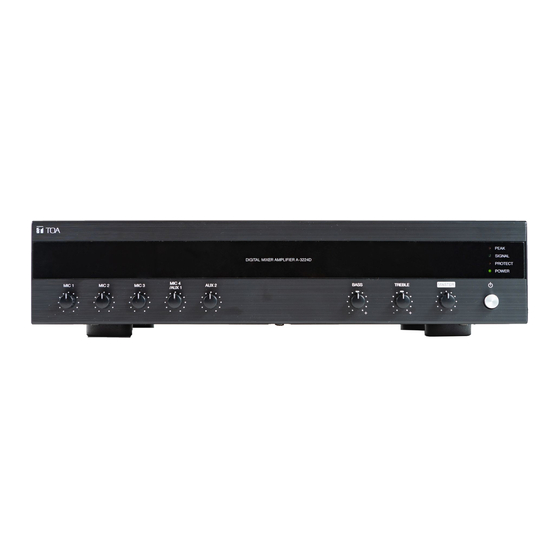
Page 4: Nomenclatures And Functions
4. NOMENCLATURES AND FUNCTIONS For A-3000D-AS Series, A-3000DM-AS Series & A-3000DMZ-AS Series [Front Panel] [Rear Panel] >PC< CAUTIO Put back this te after connecting 24 26 Note. not connected For A-3248DME-AS [Front Panel] [Rear Panel] >PC< CAUTIO Put back this te after connecting Note. - Page 5 6. Volume Control for MIC 20. Zone Selector Terminal Ad ust the microphone le el. erminal for one selector (high impedance). A aila- ble only for A-3212DMZ-AS A-3224DMZ-AS and 7. Volume Control for MIC 4/AUX 1 A-3248DMZ-AS. Ad ust le el for M 4 AU 1 hiche er acti ated 21.
- Page 6 [MP3 Panel] 38 32 35 36 32. AUX REC/PSET 36. Mode n Au mode pressing this button ill record to SD hen the unit is turned O pressing this button card. f SD card is not inserted to the slot the unit for 3 seconds ill turn off the unit.
-
Page 7: About Operating Mp3
5. ABOUT OPERATING MP3 MP3 Player Operating Mode Indication - Press button MODE a. USB & SD install while USB & SD install MODE Display mode AUX Display mode FM Display mode USB Display mode Bluetooth Display mode SD USB install * MP3 Mode (USB or SD) /AUTO - Playing normal condition. -
Page 8: Muting Function
M 3 layer Operating Mode ndication M Mode M Mode - ress button AU enter the station sa ing mode. - ress A to sa e the current fre uency as a station Display normal play initial fre uency - ress button AU for 3 sec M Mode to actually sa e this fre uency to... -
Page 9: Speaker Connections
7.2. Speaker Connections mpedances indicate at the terminal represent the total impedance (load) of the spea er system. mpedance can be s itched from high impedance to lo impedance (4 otal impedance for 100 line : (A-3212DM-AS A-3212DMZ-AS) (A-3224D-AS A-3224DM-AS A-3224DMZ-AS) (A-3248D-AS A-3248DM-AS A-3248DMZ-AS A-3248DM -AS) Using Screw Terminal Using 5 Zones Selector Terminal... - Page 10 Example of External Equipment Connections (5 zone selector , 3 mic input) Dynamic Microphone (PHANTOM switch “OFF”) or Condenser Microphone (PHANTOM switch ”ON”) Recording Device To AC Power Source Select to AUX 1 Select to left Zone 1 : Horn Speaker Dynamic Microphone Dynamic Microphone Zone 2 : Horn Speaker...
-
Page 11: Block And Level Diagrams
8. BLOCK AND LEVEL DIAGRAMS [A-3000D Series, A-3000DM Series, A-3000DMZ-Series]... - Page 12 [A-3248DME-AS]...
-
Page 13: Dimensional Diagram
9. DIMENSIONAL DIAGRAM Dimensional diagram represent by A-3248DMZ-AS image. Outer dimension for all series are same. Units : mm (inches) 420(16.54) 357(14.06) 40(1.57) -
Page 14: Specifications
10. SPECIFICATIONS A-3000D-AS 1 Series, A-3000DM-AS 1 Series Model no. A-3224D-AS 1 A-3248D-AS 1 A-3212DM-AS 1 A-3224DM-AS 1 A-3248DM-AS 1 o er Source 100 - 240 50 60 o er onsumption ( 60065) ated Output 60 d alanced hone ac selectable to –... - Page 15 A-3000DMZ-AS 1 Series, A-3248DME-AS 1 Model no. A-3212DMZ-AS 1 A-3224DMZ-AS 1 A-3248DMZ-AS 1 A-3248DM -AS 1 o er Source 100 - 240 50 60 o er onsumption ( 60065) ated Output – 60 d alanced hone ac selectable to 2 - 3 60 d alanced hone ac...
- Page 16 URL : http://www.toa.com.sg/ 133-02-00499-00...
Need help?
Do you have a question about the A-3000D-AS Series and is the answer not in the manual?
Questions and answers