Toa 800D Series Operating Instructions Manual

Toa 800D Series Operating Instructions Manual

Mixer amplifier
Hide thumbs Also See for 800D Series:

Advertisement

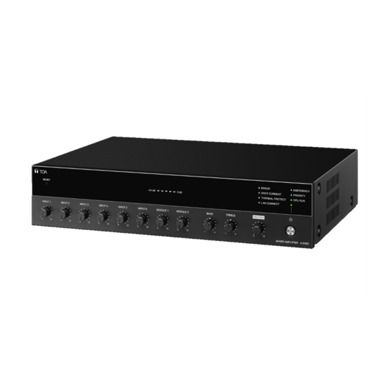
800D SERIES MIXER AMPLIFIER
Note on Firmware Upgrade
Before using the device, upgrade the firmware.
The latest firmware can be downloaded from the product page of the A-812D, A-824D, A-848D on
the TOA Corporation website.
Thank you for purchasing TOA's 800D Series Mixer Amplifier.
Please carefully follow the instructions in this manual to ensure long, trouble-free use of your equipment.
OPERATING INSTRUCTIONS
A-812D, A-824D, A-848D
The figure represents the A-812D.

Advertisement

Table of Contents
loading
Need help?

Need help?

Do you have a question about the 800D Series and is the answer not in the manual?

Questions and answers

Subscribe to Our Youtube Channel

Summary of Contents for Toa 800D Series

  • Page 1 The latest firmware can be downloaded from the product page of the A-812D, A-824D, A-848D on the TOA Corporation website. Thank you for purchasing TOA’s 800D Series Mixer Amplifier. Please carefully follow the instructions in this manual to ensure long, trouble-free use of your equipment.
  • Page 2: Table Of Contents

    TABLE OF CONTENTS 1. IMPORTANT SAFETY INSTRUCTIONS ........... 3 2. SAFETY PRECAUTIONS ................4 3. GENERAL DESCRIPTION ................6 4. FEATURES ......................6 5. HANDLING PRECAUTIONS ..............6 6. INSTALLATION PRECAUTIONS ............. 7 7. THE DUCKER FUNCTION AND THE PRIORITY BROADCAST FUNCTION ........
  • Page 3: Important Safety Instructions

    1. IMPORTANT SAFETY INSTRUCTIONS • Read these instructions. • Keep these instructions. • Heed all warnings. • Follow all instructions. • Do not use this apparatus near water. • Clean only with dry cloth. • Do not block any ventilation openings. Install in accordance with the manufacture’s instructions. •...
  • Page 4: Safety Precautions

    AC outlet and personal injury. contact your nearest TOA dealer. Make no further attempt to operate the unit in this condition as this When Installing the Unit may cause fire or electric shock.
  • Page 5 When the Unit is in Use • Contact your TOA dealer as to the cleaning. If dust is • To avoid electric shocks, be sure to switch off the allowed to accumulate in the unit over a long period unit’s power when connecting speakers.
  • Page 6: General Description

    3. GENERAL DESCRIPTION TOA's 800D Series mixer amplifier is a PA amplifier equipped with 4 microphone inputs, 2 auxiliary inputs, and 2 slots dedicated to the 900 Series modules. It employs a PFC circuit. It also features the following functions: Volume control function, Priority function, Chime function, and Remote confirmation function.
  • Page 7: Installation Precautions

    6. INSTALLATION PRECAUTIONS • The supplied power supply cord is designed for exclusive use with the unit. Never use it with other equipment. • Install the unit in a well-ventilated environment so that temperature inside the unit will not rise. •...
  • Page 8: Nomenclature And Functions

    • Lights when in the manual mode. Perform the following steps before pressing the Reset ( See the separate setup manual, which can be key. downloaded from the TOA DATA Library (https:// • Turn all volume knobs fully counterclockwise to www.toa-products.com/international/).) minimize the volume value.
  • Page 9: Rear

    13. Volume control knobs for Module inputs 1 and 2 15. Treble control knob Adjust the volume values of the rear-mounted Rotate the knob clockwise to boost the treble and modules. Rotate each knob clockwise to increase counterclockwise to cut it. the volume value and counterclockwise to Setting the knob at the center makes the frequency decrease it.
  • Page 10 19. Remote master volume control terminal 26. Input setting switches (Inputs 1 and 2) Short-circuit current: 10 mA or less, Set the input sensitivity level (LINE or MIC) of open voltage : 35 V DC or less, the Inputs 1 and 2 (27). When switched to the removable terminal block (3.50 mm, 4 pins) microphone input, set the phantom power to ON Sound volume can be adjusted by connecting the...
  • Page 11 32. Speaker output terminal 35. Recording output jacks Removable terminal block (5.00 mm, 3 pins) 0 dB*, 600 Ω, unbalanced type, RCA jack x 2 Outputs the audio signals of the MAIN output or Outputs the audio signals of the SUB output. power amplifier output.
  • Page 12: Connections

    9. CONNECTIONS External cable wiring must be only carried out by qualified and trained personnel. 9.1. Speaker Connection For cable wiring to the removable terminal block, refer to p. 18. A-812D/824D/848D Notes • Never make connection to both 4 Ω (low impedance) and 70 V line (high impedance) terminals simultaneously.
  • Page 13: Input Terminal Connections And Settings

    9.2. Input Terminal Connections and Settings 9.2.1. Connections Inputs 3 and 4 Inputs 1 and 2 A-812D/824D/848D Inputs 5 and 6 Removable terminal block Inputs 5 and 6 RCA Pin jack The terminal used for each of the Inputs 5 and 6 differs depending on the Input setting switches (input 5 and 6). (See the next page.) Connect the cable to the correct terminal according to the input terminal to use.
  • Page 14 9.2.2. Inputs 1 through 6 settings Each of Inputs 1 through 6 has its own setting switch corresponding to each input. Perform their settings as shown below as needed. [Inputs 1 and 2] Set the sound source level to connect and whether or not to use the phantom power when the microphone input is selected.
  • Page 15: Connecting To The Remote Master Volume Control Terminal

    9.3. Connecting to the Remote Master Volume Control Terminal You can remotely control the unit’s volume level by connecting a volume controller. To remotely control the volume level, adjust the unit’s volume level with the master volume control knob in advance.
  • Page 16: Connecting To The Emergency Control Output Terminal

    9.6. Connecting to the Control Input Terminal Priority broadcast can be controlled by inputting the contact signal to these terminals. For the priority setting, refer to the separate setup manual, which can be downloaded from the TOA DATA Library (https://www.toa-products.com/international/).
  • Page 17: Connecting The External Equipment Between The Pre-Amplifier Output And The Power Amplifier

    9.7. Connecting the External Equipment between the Pre-amplifier Output and the Power Amplifier Appropriate sound can be obtained by connecting a signal processor like an equalizer or limiter between the unit’s preamplifier section (Pre-amplifier output jack) and the power amplifier section (Power amplifier input jack).
  • Page 18: Removable Terminal Plug Connection

    9.8. Removable Terminal Plug Connection Step 1. Wiring the supplied removable terminal plug. [Recommended type of screwdriver ] 1-1. Loosen the terminal screws to insert the wire. 1-2. Tighten the terminal screws. Blade width* Ensure that the wire does not break free when pulled.
  • Page 19: Settings

    10. SETTINGS 10.1. Chime Tone Setting Set the chime tone to use with the DIP switches 1 and 2. A-812D/824D/848D Chime tone to use Switch 1 Switch 2 Switch’s figures 4-note (Factory-preset) 1 2 3 4 5 6 2-note 1 2 3 4 5 6 1-note 1 2 3 4 5 6 Not used...
  • Page 20: Ducker Depth Adjustment

    The front-mounted emergency broadcast indicator lights during emergency broadcast, making the Emergency control output terminal closed. Adjust the Software master volume control using the browser. For details, refer to the separate setup manual, which can be downloaded from the TOA DATA Library (https://www.toa-products.com/international/). Volume control knobs for each input remain effective.
  • Page 21: Installing To An Equipment Rack

    13. INSTALLING TO AN EQUIPMENT RACK When installing the unit to an equipment rack, remove the four plastic feet screwed on the unit’s base as shown below. Plastic foot A-812D/824D/848D When installing the unit to an equipment rack, use the supplied rack mounting brackets. Plain washer (accessory) Machine screw M4 x 16 (accessory)
  • Page 22: Priority Broadcast Function

    You can edit the following items related to the priority broadcast on the browser for each trigger. Designated audio signals can be muted in the case of normal broadcast that is not activated by any trigger. For details, refer to the separate setup manual, which can be downloaded from the TOA DATA Library (https://www.toa-products.com/international/). Item...
  • Page 23: Emergency Broadcast

    Use this mode to check the device operation. (See the separate setup manual*.) The unit’s Network connection confirmation indicator lights in the manual mode. * Can be downloaded from the TOA DATA Library (https://www.toa-products.com/international/). 15.3. Emergency Broadcast You can set the priority broadcast with the highest priority level to the emergency broadcast.
  • Page 24: Factory Default Settings

    15.6. Factory Default Settings [Factory default setting list] Audio inputs Module Trigger Priority level Emergency Chime Status Control input 1 Valid Control input 2 – Valid High Control input 3 – Valid – Control input 4 Valid Audio detection – Invalid (Input 1) Audio detection...
  • Page 25: Settings On The Browser

    For the details of the browser settings, refer to the separate setup manual, which can be downloaded from the TOA DATA Library (https://www.toa-products.com/international/).
  • Page 26: Block Diagram

    17. BLOCK DIAGRAM...
  • Page 27: Specifications

    18. SPECIFICATIONS MODEL A-812D A-824D A-848D Power Source 120 V AC, 60 Hz Rated Output 120 W 240 W 480 W Power/Current 170 W(rated output), 317 W (rated output), 621 W (rated output), Consumption 46 W (based on UL62368), 62 W (based on UL62368), 103 W (based on UL62368), 200 mA or less 200 mA or less...
  • Page 28: Accessories

    Modifications Any modifications made to this device that are not approved by TOA Corporation may void the authority granted to the user by the FCC to operate this equipment.

This manual is also suitable for:

A-812dA-824dA-848d

Table of Contents