Table of Contents
Advertisement
SYSTEM MANAGEMENT AMPLIFIER
REMOTE MICROPHONE
REMOTE MICROPHONE EXTENSION
VOICE ANNOUNCEMENT BOARD
SURVEILLANCE BOARD
VM-2120
Please follow the instructions in this manual to obtain the optimum results from this unit.
We also recommend that you keep this manual handy for future reference.
INSTRUCTION MANUAL
VM-2120 (120 W)
VM-2240 (240 W)
RM-200M
RM-210
EV-200
SV-200M
RM-200M
Advertisement
Table of Contents

Subscribe to Our Youtube Channel
Related Manuals for Toa SV-200M


Summary of Contents for Toa SV-200M
- Page 1 REMOTE MICROPHONE EXTENSION RM-210 VOICE ANNOUNCEMENT BOARD EV-200 SURVEILLANCE BOARD SV-200M RM-200M VM-2120 Please follow the instructions in this manual to obtain the optimum results from this unit. We also recommend that you keep this manual handy for future reference.
-
Page 2: Table Of Contents
TABLE OF CONTENTS 1. SAFETY PRECAUTIONS ..................4 EQUIPMENT OUTLINES 2. GENERAL DESCRIPTION ................... 6 3. FEATURES ......................6 4. HANDLING PRECAUTIONS ................7 5. INSTALLATION PRECAUTIONS ................ 7 6. NOMENCLATURE AND FUNCTIONS 6.1. System Management Amplifier VM-2120/-2240 ..........8 6.2. - Page 3 16. MOUNTING AN OPTIONAL SV-200M SURVEILLANCE BOARD ..............31 17. RACK MOUNTING ....................32 AMPLIFIER CONNECTIONS 18. AMPLIFIER INPUT CONNECTION 18.1. Two Amplifiers Stack-Connection ..............32 18.2. Microphone Connection to the VM Amplifier ..........32 18.3. Telephone Paging Input Connections ............33 19.
-
Page 4: Safety Precautions
Refer all servicing to surface. Doing so may result in the unit falling your nearest TOA dealer. down and causing personal injury and/or property damage. • Do not place cups, bowls, or other containers of liquid or metallic objects on top of the unit. - Page 5 • Avoid installing the unit in humid or dusty locations, in locations exposed to the direct sunlight, near the • Contact your TOA dealer as to the cleaning. If dust heaters, or in locations generating sooty smoke or is allowed to accumulate in the unit over a long...
-
Page 6: General Description
2. GENERAL DESCRIPTION [System Management Amplifier VM-2120/VM-2240] Featuring outstanding audio performance, the TOA System Management Amplifier VM-2120/-2240 satisfies the growing need for reliable and efficient communications for various applications, especially for medium- sized facilities including office building, factories, hospitals, and transportation terminals. -
Page 7: Handling Precautions
4. HANDLING PRECAUTIONS [VM-2120/VM-2240 and RM-200M/RM-210] To clean, be sure to first switch off the power supply to the unit, then wipe with a dry cloth. When the unit gets very dirty, use a cloth damped in a neutral cleanser. Never use benzene, thinner or chemically-treated cleaning cloth because such volatile liquids could deform or discolor the unit. -
Page 8: Nomenclature And Functions
6. NOMENCLATURE AND FUNCTIONS 6.1. System Management Amplifier VM-2120/-2240 [Front] 6 7 10 The VM-2120 is shown in the figure. The VM-2240 is the same in both appearance and function. 1. Power switch [POWER] Flashes to show the speaker zone which is being Turns on and off the power. - Page 9 [Rear] SV-200M EV-200 30 19 The figure above shows the 230 V AC versions of the VM-2120 and VM-2240. The 120 V AC versions are the same in both appearance and function except the rating indications of the AC inlet (No. 33) and fuse holder (No. 34).
- Page 10 (2) Control input for broadcast activation (2) External speaker line Input [CTRL IN 1, 2, 3] [EXTERNAL SP INPUT] 3 no-voltage make contact inputs, open voltage: Accepts the signal from the external amplifier's 3.3 V DC, short-circuit current: under 1 mA speaker line.
- Page 11 Broadcast will terminate the broadcast without completion. [Surveillance Board SV-200M] The following functions No. 41 through No. 43 are used when an optional SV-200M Board is mounted in the unit. 41. Surveillance input and output connector case, the indicators of all zones flash to [SURVEILLANCE I/O] indicate the broadcast is in pause.
-
Page 12: Remote Microphone Rm-200M
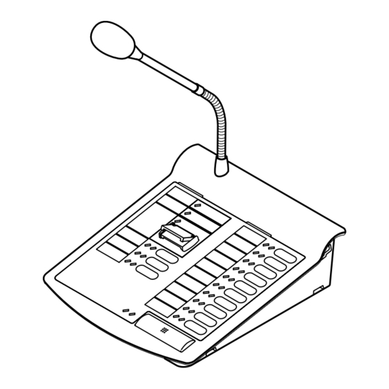
6.2. Remote Microphone RM-200M [Top] 10. All-zone broadcast key (ALL-ZONE) Press this key to make the All-Zone Broadcast. 11. Zone selector key (ZONE 1 – 5) Selects the desired broadcast zones (Zones 1 – 5). 12. Zone indicator (ZONE 1 – 5) Lights green when the corresponding broadcast zone (Zones 1 –... -
Page 13: Remote Microphone Extension Rm-210
[Rear] [Right Side] 18. DC power input jack [DC POWER IN] • A jack with non-polarity. Connect the 24-V DC power (AC adapter). (See the specifications on p. 59.) • The VM amplifier can supply the power to only 21. External microphone input jack a single Remote Microphone. -
Page 14: System Configurations
7. SYSTEM CONFIGURATIONS 7.1. Remote Microphone/VM Amplifier Configuration (The Number of Connected Units) Set the total number (0 – 5) of equipment (up to 1 sub-VM amplifier and up to 4 RM-200M Remote Microphones) connected to the master VM amplifier using the master VM amplifier's internal DIP switches SW3-No. -
Page 15: Connection Between Remote Microphone And Vm Amplifier
(3) 10 speaker zones with 2 VM amplifiers Remote Master VM amplifier microphone RM-200M Zone 1 – 10 Zone 1 – 5 selector key/indicator selector key/indicator Sub-VM amplifier Zone 6 – 10 selector key/indicator (4) 10 speaker zones with 2 VM amplifiers (equipped with the EV-200 Board) Voice announcement board EV-200 Remote... -
Page 16: Power Supply From The Vm Amplifier To Remote Microphone
Connection example 2 Link cable* LINK connector (RJ45) Master VM Sub-VM Remote Remote Remote Remote amplifier amplifier microphone microphone microphone microphone 24 V DC 24 V DC 24 V DC Power Power Power PRE OUT jack POWER AMP IN jack supply supply supply... -
Page 17: Emergency ("Alert" And "Evacuation") Broadcast
8. EMERGENCY ("ALERT" AND "EVACUATION") BROADCAST 8.1. Emergency Broadcast Equipment Emergency alert activation input Emergency evacuation activation input Emergency stop activation input Speaker External equipment (ex. fire alarm system) CONTROL I/O connector VM amplifier (VM-2120/-2240) LINK connector Remote microphone (RM-200M) 8.2. -
Page 18: Emergency Broadcast Operation (Typical Example)
8.3. Emergency Broadcast Operation (Typical Example) Step 1. Alert Broadcast Open the RM-200 Remote Microphone's Emergency broadcast EMERGENCY switch cover, and press the switch. A pre-recorded Alert signal tone and Alert announcement will be alternately broadcast to the entire zone for the preset number of Alert repetitions.* The EMERGENCY indicators of the RM-200M and the... - Page 19 Step 4. Emergency Broadcast Termination To terminate the Emergency broadcast, activate the Emergency Stop input by way of the corresponding connected external equipment. The unit returns to the general-purpose broadcast mode it was in immediately before the Emergency broadcast was started. Then, both EMERGENCY indicators of the RM-200M and the VM amplifier go out.
-
Page 20: Emergency Broadcast Sequence
8.4. Emergency Broadcast Sequence General-purpose broadcast Depression of the Remote Activation of Alert input* Activation of Evacuation input* Microphone's Emergency by external equipment. by external equipment broadcast switch Alternate repetition of Alert tone signal Alternate repetition of Evacuation tone and Alert announcement signal and Evacuation announcement End of set repetition Live microphone... -
Page 21: Broadcast Operation At The Amplifier
For connection of the control input (CTRL 1 – 3), refer to p. 32. Notes • TOA's Paging Microphone PM-660D (for Input 1) is equipped with the talk key. • When using a commonly-used microphone, the press-to-talk switch needs to be made. -
Page 22: Remote Microphone General-Purpose Broadcast
10. REMOTE MICROPHONE GENERAL-PURPOSE BROADCAST 10.1. Operation and Display Sections The panel functions of the operation and display sections differ depending on the amplifier configuration (5 zones or 10 zones) and the use of the Recorded Message Announcement function. The figure shows an example of the operation panel function for a 5-zone single amplifier configuration with the Voice Announcement Board. -
Page 23: Broadcast Operation
10.2. Broadcast Operation Following 4 types of broadcasts are possible: All-Zone, Individual Zone, Group, and Message Broadcasts. This section describes how to make each broadcast. (1) Simultaneous All-Zone Broadcast Operation Step 1. Press the ALL-ZONE key. ALL-ZONE The All-zone indicator and all zone indicators (1 – 5) will light. (Press the ALL-ZONE key again to cancel.) Go to Step 2 on the next page. - Page 24 (4) Message Broadcast Operation Messages (1 – 5) assigned to broadcast groups require to be programmed into the VM amplifier. (See p. 52 "Recorded Message-to-Group assignment.") Example of Message 1 broadcast Group 1 Zone 1 Message 1 (Selected) Zone 2 Broadcast Zones Zone 3...
- Page 25 3-2. After chime play completion, make an announcement using the microphone. Live microphone announcements TALK key Step 4. End of broadcast TALK Releasing the Talk key will sound an end chime tone (only when the Up/Down 4-tone chime function is employed by the unit), terminating the broadcast.
-
Page 26: General-Purpose Broadcast Priority
11. GENERAL-PURPOSE BROADCAST PRIORITY 11.1. Broadcast Source-to-Priority Relationship • Making broadcast with higher priority cuts off the current lower-priority broadcast, allowing the higher priority broadcast to go through. Upon completion of the higher priority broadcast, the original broadcast is automatically restored. For background music (BGM) broadcast (Priority 4), it is also possible to mix it with other broadcasts or reduce its sound volume without cutting it off. -
Page 27: Broadcast Priority Between Equipment With The Equal Priority Level
11.2. Broadcast Priority between Equipment with the Equal Priority Level 11.2.1. Priority mode between equipment with the equal priority level The following 3 priority modes are made available, which can be set using the unit's internal SW2-No. 8 and SW3-No. 1 switches. (1) Last-come-first-served priority (factory-preset mode) The latest broadcast takes precedence, with the earlier broadcast interrupted. -
Page 28: Priority Function When 2 Broadcasts With The Equal Priority Level Are Simultaneously Made
11.2.2. Priority function when 2 broadcasts with the equal priority level are simultaneously made When two or more broadcasts with the equal priority level are simultaneously made, priority mode is as shown in the following table depending on the type of broadcast sound source and setting switch status. Competing priority level (Priority level of simultaneously made broadcasts) Broadcast sound source... -
Page 29: Chime Function
12. CHIME FUNCTION 12.1. Available Chime Tone Types There are 7 different chimes (one of which can be selected for a pre-announcement chime), and a Westminster chime for a time signal. 12.1.1. Seven different chime tones • Six built-in chimes, and 1 pre-recorded chime that is made by recording any preferred sound source are made available for selection. -
Page 30: Independent Chime Activation (Remote Control)
12.2.3. Independent chime activation (remote control) • A chime tone can be sounded when the broadcast of the sound source (Priority 3) connected to Inputs 1 – 3 not activated by remote control (CTRL IN 1,2,3) is started (and completed). •... -
Page 31: Westminster Chime
The work must be done by a qualified service technician only. For the mounting method, consult the shop from whom the unit or the board was purchased. 16. MOUNTING AN OPTIONAL SV-200M SURVEILLANCE BOARD The work must be done by a qualified service technician only. -
Page 32: Rack Mounting
Step 4. Mount the unit on an equipment rack using the Bracket's accessory screws and fiber washers. Note: When mounting the unit in an equipment rack not made by TOA, prepare separately the screws and washers appropriate for the rack. -
Page 33: Telephone Paging Input Connections
18.3. Telephone Paging Input Connections E C H When using a single-core shielded cable, connect the shielded mesh to PBX, main telephone device, etc. both E and C terminals. Control signal Audio signal Telephone line... -
Page 34: External Attenuator Control Wiring
19. EXTERNAL ATTENUATOR CONTROL WIRING 19.1. 4-Wire System Connection ATTENUATOR CONTROL relay contact capacity Withstand voltage: 30 V DC, 125 V AC Contact current: Under 7 A (DC), under 7 A (AC) VM amplifier N1 (NC) ATTENUATOR External DC power supply CONTROL* to activate attenuators –... -
Page 35: 3-Wire System Connection
19.2. 3-Wire System Connection Note: 3-wire system cannot be used with the SV-200M board. ATTENUATOR CONTROL relay contact capacity Withstand voltage: 30 V DC, 125 V AC Contact current: Under 7 A (DC), under 7 A (AC) VM amplifier N1 (NC) -
Page 36: Control I/O Connector Functions
21. CONTROL I/O CONNECTOR FUNCTIONS The rear panel-mounted Control I/O connector enables the VM amplifier to be controlled or monitored by connected external equipment. Referring to the pin arrangement and functions, prepare the matching D-sub male connector (screw-lock type) for connection to the external equipment. (See p. 10 No. 30 CONTROL I/O connector.) VM amplifier's D-sub female connector CONTROL I/O... - Page 37 Signal name Signal/logic Function/status /OUT Communications error Active Low When communications cannot be achieved between the RM-200M and the VM amplifier or between VM amplifiers (High state when communications are restored.) Failure indication Active Low When the FAULT indicator lamp is on Emergency broadcast Active Low When an Emergency broadcast is performed...
-
Page 38: Surveillance I/O Connector Functions
D-sub male connector (screw-lock type) for connection to the external equipment. (See p. 11 No. 41 SURVEILLANCE I/O connector.) * Requires installation of the optional SV-200M Surveillance Board. SV-200M's D-sub female connector... -
Page 39: Settings
[Electrical characteristics] Input Open voltage: 3.3 V DC Short-circuit current: Under 1 mA Activation: No-voltage make contact (one-shot signal is shown below.) Over 100 ms Output Circuit: Open collector (See below.) Withstand voltage: 30 V DC Control current: Under 10 mA Control current 23. -
Page 40: Vm Amplifier's Internal Function Switches
23.2. VM Amplifier's Internal Function Switches The switches must be set by a qualified service technician only. Each of the following functions can be selectively set with the switches. For the switch setting method, consult the shop from whom the unit was purchased. Priority levels (Underlined priority levels represent factory-preset levels.) Function Inputs 1 –... -
Page 41: Broadcast Group/Zone Setting
24. BROADCAST GROUP/ZONE SETTING 24.1. Routing Assignment 24.1.1. Zone-to-Group assignment Desired broadcast zones (1 – 10) can be combined into one broadcast group (Groups 1 – 5). (See p. 43 "Zone-to-Group Assignment Operation.") Setting example ( mark indicates "Set" state.) Setting content Broadcast Group Broadcast Zone 1 –... -
Page 42: Recorded Message-To-Group Assignment
24.1.3. Recorded Message-to-Group assignment Activated messages (1 – 5) are broadcast to their respectively assigned groups 1 – 5. (See p. 48 "Recorded Message-to-Group Assignment Operation.") Setting example ( mark indicates "Set" state.) Setting content Recorded Message Broadcast Group ALL zones (Marking a check bypasses the (Setting item) external attenuator on all-zone broadcast.) Message 1... -
Page 43: Zone-To-Group Assignment Operation
24.3. Zone-to-Group Assignment Operation • Here, the operation example of assigning Broadcast Zones 2 – 4 to Group 2 will be explained for a 5-zone (Master unit only) configuration. (See p. 41 "Group 2 to zone" setting example.) • In the case of 10 broadcast zones (i.e. connection of a master unit to a sub-unit), use the sub-unit's Zone selector keys 1 –... - Page 44 Step 4. Zone number setting (Example: Zones 2, 3, and 4) Press the ZONE 3 and ZONE 4 keys to select the corresponding zones. (As a result, The Zones 2, 3, and 4 are selected.) • Indicators for ZONE 3 and ZONE 4 will light. Zone 1 Group 2 Zone 5...
- Page 45 [Group setting contents check] Complete Steps 1, 2, and 3, then jump to Steps 5 and 6 without executing Step 4 (zone number setting). [Indicator status] (1) Flashing Equal duration "ON" and "OFF" indicator flashing. Indicates that the corresponding setting contents (Example: Zone number) have not yet been selected (setting contents can be selected).
-
Page 46: Control Input/Telephone Paging /Westminster Chime-To-Group Assignment Operation
[Operation for zone selection and its cancellation] • Pressing a currently flashing or quickly flashing zone key for any zone not selected will select that zone (the zone indicator then remains steadily lit or slowly flashes). • Conversely, if a currently selected zone key is pressed, that zone will then be deselected. ("Selected" and "deselected"... - Page 47 Step 4. Group number setting (Example: Groups 1, 2, and 3) Group 1 Group 5 4-1. Pressing the ALL key will cancel the "ALL zones" (Input 1) setting, causing the ALL indicator and the indicators for ZONES 2 – 5 to flash. The ZONE 1 indicator changes from "slow flashing"...
-
Page 48: Recorded Message-To-Group Assignment Operation
24.5. Recorded Message-to-Group Assignment Operation Here, the operation example of assigning Recorded Message 1 to Broadcast Groups 1, 3, and 4 will be explained. (See p. 42 "Message 1 to group" setting example.) ZONE 1 ZONE 3 Reset Step 1. Entry to recorded message setting mode Press and release the Reset key while holding down the ZONE 1 and ZONE 3 keys. -
Page 49: Linkage Between Remote Microphone And Its Extension
25. LINKAGE BETWEEN REMOTE MICROPHONE AND ITS EXTENSION When adding the RM-210 Remote Microphone Extension, link it with the RM-200M Remote Microphone using the extension cable and mounting hardware supplied with the RM-210. Step 1. Turn over both the RM-200M and the RM-210, and keep them in close contact with each other. Step 2. -
Page 50: Name Label Preparation
26. NAME LABEL PREPARATION 26.1. Amplifier's Label Preparation • Use the supplied labels to indicate the names of each input and output on the front panel. Write the name in the label, and affix it under each input or output volume control. See p. 8 "NOMENCLATURE AND FUNCTIONS"... - Page 51 [Pattern paper for hand writing] Name label A Name label B Cutting guideline Shown in actual size...
- Page 52 [Dimensional diagram for printing devices] Name label A Name label B Cutting size: 30 x 108 mm Cutting size: 30 x 134 mm POWER ZONE 1 FAULT ZONE 2 ZONE 3 EMERGENCY ZONE 4 ACTIVATION ZONE 5 GROUP 1 MESSAGE 1 GROUP 2 MESSAGE 2 MESSAGE 3...
-
Page 53: Compactflash (Cf) Card Recording
27. COMPACTFLASH (CF) CARD RECORDING 27.1. Recording • Use TOA's EV-350R Digital Announcer for CF card recording. • The table below shows an example of Program/Sentence composition for Messages 1 – 8. [Setting items and contents] (1) Set the items in "Program No." (P001 – P008) and "Playback method" columns as shown in the table. -
Page 54: Message Program Example
27.3. Message Program Example The programs shown in "Message Program/Sentence Composition Example" on the previous page operate as follows. (1) General-purpose broadcast message (Program No. 1) [Continuous program playback method] Step No. Program P001 Activation 1st sentence A001 2nd sentence A002 Playback Silent interval 3 seconds... -
Page 55: Block Diagram
28. BLOCK DIAGRAM [VM-2120/-2240]... -
Page 56: Specifications
29. SPECIFICATIONS System Management Amplifier VM-2120/-2240 Model No. VM-2120 VM-2240 Power Source AC: 120 V or 230 V AC, 50/60 Hz DC: 24 V DC/7.5 A (VM-2120), 15 A (VM-2240), M3.5 screw terminal, Barrier distance: 8 mm, Applicable cable gauge: AWG22 –... - Page 57 Model No. VM-2120 VM-2240 Audio Speaker Output Rated output (volume control in maximum position), Plug-in screw Output connector* 5-zone selector with attenuator (all zones simultaneously selectable) Speaker Selector Direct output from the power amplifier output transformer Direct Speaker Line (attenuator bypassed), Plug-in screw connector* Output 0 dB* , 10 kΩ, RCA pin jack...
- Page 58 The messages and chime sound source must be pre-recorded into a CF (CompactFlash) card to be inserted into the EV-200 Board. An optional SV-200M Surveillance Board is required. Usable cable gauge: AWG26 – AWG20 Usable cable gauge: AWG24 – AWG12...
-
Page 59: Remote Microphone Rm-200M
Remote Microphone RM-200M Power Source 24 V DC (Operating range: 14 – 28 V DC) Power input jack: Non-polarity type Usable power input plug* : Outer diameter ø5.5 mm, inner diameter ø2.1 mm, length 9.5 mm Current Consumption 100 mA maximum Distortion Under 1% Frequency Response... -
Page 60: Voice Announcement Board Ev-200
Screw for linkage bracket ................. 12 Voice announcement board EV-200 Mounting screw ................... 2 • Optional products For both VM-2120 and VM-2240 Rack mounting bracket MB-36 Choke coil CT-200M Input transformer IT-450 Voice Announcement Board EV-200 Surveillance Board SV-200M 133-12-726-70...
Need help?
Do you have a question about the SV-200M and is the answer not in the manual?
Questions and answers