Advertisement
Intermittent Pilot Dual Automatic
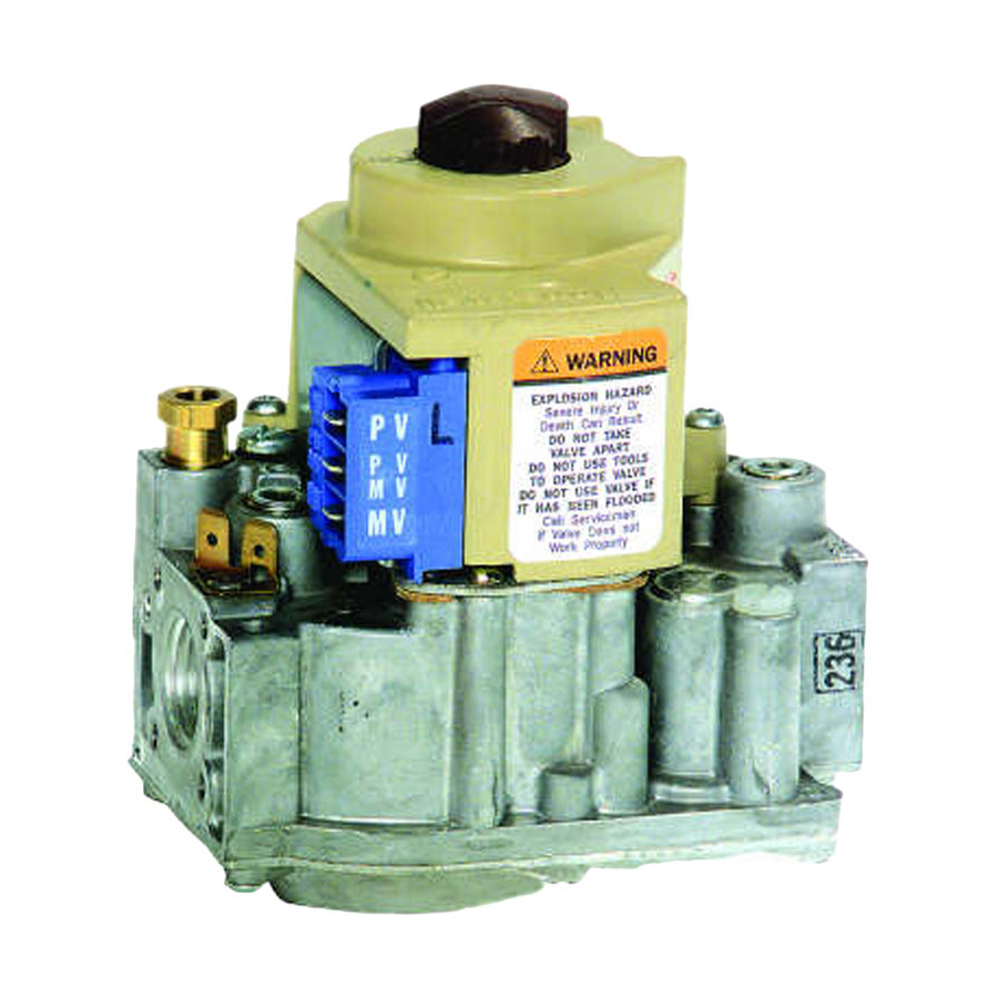
Valve Combination Gas Controls
The VR8204 AND VR4204 Intermittent Pilot
Dual Automatic Valve Combination Gas Controls
are used in gas-fired, intermittent pilot appli-
ances. The controls include a safety shutoff, a
manual valve, two automatic operators, a pres-
sure regulator, a pilot adjustment screw and a
conduit cover (VR4204 only).
VR8204 used with S8600, S8610 and S8620 Control
Modules.
VR4204 used with 120 Vac intermittent ignition mod-
ules.
VR8204 for use with 24 Vac heating appliances and
VR4204 for use with 120 Vac heating appliances that
burn natural or manufactured gas, or liquified petroleum
(LP) gas.
Capacity rated at 150 cfh at 1 in. wc pressure drop
3
[4.2 m
/hr at 0.25 kPa].
Solenoid-operated first automatic valve opens on ther-
mostat call for heat and closes when call for heat ends.
Diaphragm-operated second automatic valve opens un-
der control of the regulator and closes if gas or power
supply is interrupted.
Two-position gas control knob has ON and OFF posi-
tions.
All adjustments and wiring connections are accessible
from top of the control.
Compact size.
Straight-through body pattern; right angle adapters avail-
able for inlet and outlet.
1/2 in. inlet and 1/2 in. outlet; adapters available for 3/8
or 3/4 in.
VR8204; VR4204
Adjustable servo regulator effectively maintains almost
constant gas output pressure under wide fluctuations in
gas supply pressure.
Inlet and outlet screens included.
Pilot filter included.
Wiring terminal block color-coded orange to indicate
intermittent pilot control.
May be installed at any angle between 0 and 90 degrees
from the upright position, including vertically.
1/4 in. male quick-connect terminals for electrical con-
nections.
0° F to 175 F° [-18° C to +79° C] temperature range
standard; -40° F to 175° F [-40° C to +79° C] available.
lnlet and outlet pressure taps provided; both taps acces-
sible from top of control.
Standard-, slow- and step-opening models available.
CONTENTS
Specifications ............................................... 2
Ordering Information .................................. 2
Installation ................................................... 4
Startup and Checkout .................................. 8
Maintenance .............................................. 10
Operation ................................................... 10
Service ........................................................ 13
G. S. • Rev. 1-94 • ©Honeywell Inc. 1994 • Form Number 68-0047-2
1
68-0047-2
Advertisement

Related Manuals for Honeywell VR8204M


Summarization of Contents
Specifications and Ordering
TRADELINE® Models
Details about TRADELINE controls for ease of stocking and maximum replacement value.
Standard Models
Details about standard VR8204 and VR4204 controls for intermittent pilot systems.
Ordering Product Information
Instructions for ordering replacement products, including specifying order number and gas type.
Installation Guide
Converting Between Natural and LP Gas
Procedures and warnings for converting the gas control between natural and LP gas systems.
Using Adapters and Piping
Instructions for using adapters, installing piping, and connecting the control to gas supply.
Location Requirements
Guidelines for selecting an appropriate mounting location for the gas control within the appliance.
Connecting Pilot Gas Tubing
Detailed steps for cutting, preparing, and connecting pilot gas tubing to the control.
Wiring Connections
Instructions and diagrams for connecting the gas control to the ignition module and other components.
Startup and Checkout Procedures
Gas Control Knob Settings and Operation
Explanation of ON/OFF positions and basic knob operation for the gas control.
Gas Leak Test Procedure
Steps for performing a gas leak test after installation or service to ensure safety.
Pilot Flame Adjustment
Instructions for adjusting the pilot flame to the correct size and position for reliable ignition.
Safety Shutdown Test
Procedure to verify the proper functioning of the safety shutdown mechanism for the intermittent pilot system.
Gas Input and Burner Ignition Adjustment
Procedures for checking and adjusting gas input and burner ignition for optimal performance.
Pressure Regulator Adjustment
Instructions for adjusting pressure regulators to match appliance ratings.
Maintenance and Operation
Preventive Maintenance Guidelines
Recommendations for regular checks and maintenance frequency based on usage and environment.
System Operation Overview
Explanation of how the gas control operates with the thermostat and intermittent pilot module.
Valve Position During Thermostat Cycles
Describes valve positions during thermostat off cycle, pilot ignition trial, and burner on cycle.
Standard and Slow-Opening Regulation
Explains how standard and slow-opening gas controls regulate gas flow and pressure.
Step-Opening Regulation
Details the operation of step-opening gas controls, including dual pressure regulation.
Service and Troubleshooting
General Service Precautions
Warnings against disassembling the gas control and cautions regarding electrical connections.
Troubleshooting: Main Burner Not On
Steps to diagnose and resolve issues when the main burner does not activate during a call for heat.
Homeowner Instructions: Turning On Furnace
Guidance for homeowners on safely turning on the furnace, including pre-operation checks.
Homeowner Instructions: Turning Off Appliance
Instructions for homeowners on how to turn off the appliance for vacation or complete shutdown.
Need help?
Do you have a question about the VR8204M and is the answer not in the manual?
Questions and answers