Honeywell VR8205 Manual
Direct ignition dual automatic valve combination gas controls
Hide thumbs
Also See for VR8205:
- Installation instructions manual (13 pages) ,
- Installation instructions manual (8 pages)
Advertisement
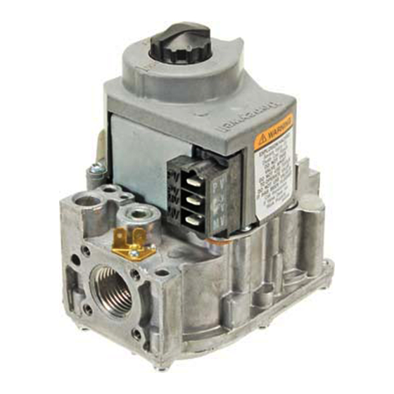
Direct Ignition Dual Automatic
Valve Combination Gas Controls
The VR8205 and VR4205 Direct Ignition Dual
Automatic Valve Combination Gas Controls are
for use with direct ignition systems in gas-fired
appliances. The controls include a safety shutoff,
a manual valve, two automatic operators and a
pressure regulator and conduit cover (VR4205
only).
VR8205 used with S89C,E,F and S87 series 5 and later.
VR4205 used with 120 Vac direct ignition modules.
VR8205 for use with 24 Vac heating appliances and
VR4205 for use with 120 Vac heating appliances that
burn natural or manufactured gas, or liquefied petroleum
(LP) gas.
Capacity rated at 150 cfh at 1 in. wc pressure drop
3
[4.2 m
/h at 0.25 kPa].
Solenoid operated first automatic valve opens on
thermostat call for heat and closes when call for heat
ends.
Diaphragm-operated second automatic valve opens under
control of the regulator and closes if gas or power supply
is interrupted.
Two-position gas control knob has ON and OFF positions.
All adjustments and wiring connections accessible from
top of the control.
Compact size.
Straight-through body pattern; right angle adapters
available for inlet and outlet.
1/2 in. inlet and 1 /2 in. outlet; adapters available for 3/8
or 3/4 in.
VR8205; VR4205
Adjustable servo regulator effectively maintains almost
constant gas output pressure under wide fluctuations in
gas supply pressure.
Inlet and outlet screens included.
Wiring terminal block color-coded brown to indicate
direct ignition control.
May be installed at any angle between 0 and 90 degrees
from the upright position, including vertically.
1/4 in. male quick-connect terminals for electrical
connections.
0° F to 175° F [-18° C to +79° C] temperature range
standard; -40° F to +175° F [-40° C to +79° C] available.
lnlet and outlet pressure taps included; both taps accessible
from top of control.
Standard-, slow- and step-opening models available.
CONTENTS
Specifications ............................................... 2
Ordering Information .................................. 2
Installation ................................................... 4
Startup and Checkout .................................. 8
Maintenance .............................................. 10
Operation ................................................... 10
Service ........................................................ 12
1
G. S. • Rev. 1-94 • ©Honeywell Inc. 1994 • Form Number 68-0049-2
68-0049-2
Advertisement


Need help?
Do you have a question about the VR8205 and is the answer not in the manual?
Questions and answers