Honeywell VR8305 Quick Manual
Direct ignition dual automatic valve combination gas controls
Hide thumbs
Also See for VR8305:
- User manual (12 pages) ,
- Installation instructions manual (13 pages) ,
- Manual (16 pages)
Advertisement
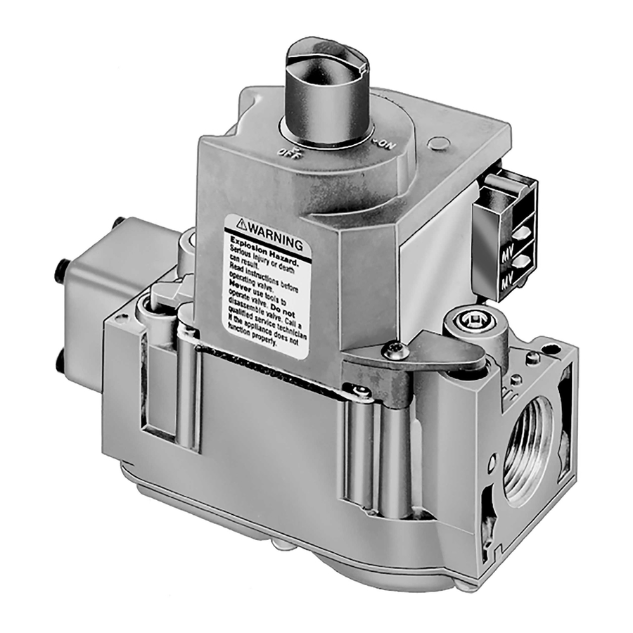
Combination Gas Controls
The VR8305 Direct Ignition Dual Automatic
Valve Combination Gas Controls are for use with
direct ignition systems in gas-fired appliances.
The controls include a safety shut-off, a manual
valve, two automatic operators, and a pressure
regulator.
Used with S89C,E,F and S87 series 5 and later.
Used with 24 Vac heating appliances that burn natural or
liquefied petroleum (LP) gas.
Capacity rated up to 300 feet
drop [8.5 meters
3
/hour at 0.25 kPa]. Maximum capacity
3
rated up to 415 feet
/hour [11.8 meters
3
capacity rated at 30 feet
/hour [0.8 meters
Solenoid operated dual first automatic valves open on
thermostat call for heat and close when call for heat ends.
Opening of the solenoid-operated second automatic valve
engages the servo pressure regulator. Loss of power or gas
closes the valve.
Two-position gas control knob has ON and OFF positions.
All adjustments and wiring connections accessible from
top of the control.
Compact size.
Straight-through body pattern; right angle adapters avail-
able for inlet and outlet.
Available in 1/2 inch and 3/4 inch inlet and outlet. 1/2 inch
and 3/4 inch straight and angle adapters available.
VR8305 Direct Ignition
Dual Automatic Valve
3
/hour at 1 inch wc pressure
3
/hour]. Minimum
3
/hour].
G.G. • Rev. 1-92 • ©Honeywell Inc. 1992 • Printed in U.S.A. • Form Number 68-0109-3
Adjustable servo regulator effectively maintains almost
constant gas output pressure under wide fluctuations in
gas supply pressure.
Inlet screen included.
Wiring terminal block color-coded brown to indicate
direct ignition control.
May be installed at any angle including vertically between
0 and 90 degrees from the upright position.
1/4 inch male quick-connect terminals for electrical con-
nections.
-40° F to +175° F [-40° C to +79° C] temperature range.
(VR8305H 0° F to 175° F [-18° C to 79° C]).
Inlet and outlet pressure taps included; both taps acces-
sible from top of control.
Standard, slow, and step-opening models available.
Natural to LP gas conversion kit included for standard-
opening and slow-opening models.
LP to natural gas conversion kit available for standard-
opening and slow-opening models.
CONTENTS
Specifications ................................................. 2
Ordering Information ..................................... 2
Installation ..................................................... 4
Start-up and Checkout .................................... 8
Maintenance ................................................. 10
Operation ..................................................... 10
Service .......................................................... 13
Advertisement

Related Manuals for Honeywell VR8305


Summary of Contents for Honeywell VR8305
-
Page 1: Table Of Contents
Specifications ..........2 Ordering Information ........2 Installation ............. 4 Start-up and Checkout ........8 Maintenance ..........10 Operation ............. 10 Service ............13 G.G. • Rev. 1-92 • ©Honeywell Inc. 1992 • Printed in U.S.A. • Form Number 68-0109—3... -
Page 2: Specifications
If you have additional questions, need further information, or would like to comment on our products or services, please write or phone: 1. Your local Honeywell Residential and Building Controls Division Sales Office (check white pages of your phone directory). - Page 3 • 393691 Natural to LP Gas Conversion Kit. TABLE 3—ADAPTER (FLANGE) PART NUMBERS. • 394588 LP to Natural Gas Conversion Kit. Part Number Inlet/ Without With Fig. 1—VR8305 installation dimensions in Outlet Flange inches and [millimeters]. Pipe Size Type Wrench...
-
Page 4: Installation
LP, use the 393691 LP Conver- SEVERE INJURY, OR DEATH sion Kit that is included with the VR8305 Gas Control. To Follow these warnings exactly: convert from LP to natural gas, use the 394588 Natural Gas 1. - Page 5 VR8305 INSTALLATION Fig. 3—Installation of conversion kit in regu- Fig. 4—Install flange to gas control. lated gas control. COLOR CODE FOR NATRUAL CAP SCREW BLACK SILVER PRESSURE REGULATOR WHITE WHITE ADJUSTING SCREW STAINLESS SPRING STEEL 9/64 INCH HEX SCREWS (4)
- Page 6 VR8305 INSTALLATION Fig. 5—Install sediment trap. Fig. 6—Use moderate amount of pipe com- pound. DROP TWO IMPERFECT THREADS GAS CONTROL PIPED HORIZONTAL CONTROL SUPPLY PIPE RISER THREAD PIPE THE AMOUNT APPLY A MODERATE AMOUNT OF CONTROL PIPED SHOWN IN TABLE FOR...
- Page 7 VR8305 INSTALLATION 1. This gas control can be mounted 0-90 degrees, in any Fig. 8—VR8305 Wiring Connections in S87 direction including vertically, from the upright position of the Direct Ignition System. gas control knob. 2. Mount the gas control so gas flow is in the direction of the arrow on the bottom of the control.
-
Page 8: Start-Up And Checkout
VR8305 START-UP AND CHECKOUT Start-Up and Checkout WARNING CHECK AND ADJUST GAS INPUT TO MAIN BURNER FIRE OR EXPLOSION HAZARD CAN CAUSE PROPERTY DAMAGE, CAUTION SEVERE INJURY, OR DEATH 1. Do not force the gas control knob. Use only your 1. - Page 9 VR8305 START-UP AND CHECKOUT a. Remove the pressure regulator adjustment cap and sure. Ensure the main burner lights smoothly and without screw. flashback to the orifice and that all ports remain lit. Cycle the b. Using a screwdriver, turn the inner adjustment screw...
-
Page 10: Maintenance
200,000 cycles. literature. Operation The VR8305 Gas Controls provide ON-OFF manual VALVE POSITION DURING THERMOSTAT OFF control of gas flow. In the OFF position, main burner gas flow CYCLE is prevented. In the ON position, main burner gas flow is The valve is positioned as shown in Fig. - Page 11 VR8305 OPERATION close control of outlet pressure, even if inlet pressure and flow main burner increases gradually from 0 inches wc [0 kPa] to rate vary widely. Any outlet pressure change is immediately rated output pressure within 3-6 seconds (for an 80,000 Btuh reflected back to the pressure regulator diaphragm, which furnace at 7 inches wc [1.8 kPa] inlet pressure and 3.5 inches...
- Page 12 VR8305 OPERATION Fig. 11—Position of gas control components during burner on cycle. CONTROL SECOND AUTOMATIC SECOND KNOB VALVE OPERATOR AUTOMATIC OPERATOR SOLENOID SERVO PRESSURE REGULATOR FIRST AUTOMATIC VALVE SOLENOID SECOND AUTOMATIC OPERATOR VALVE DISC CONTROL INLET CONTROL OUTLET FIRST AUTOMATIC VALVE...
-
Page 13: Service
VR8305 SERVICE Service WARNING WARNING FIRE OR EXPLOSION HAZARD FIRE OR EXPLOSION HAZARD CAN CAUSE PROPERTY DAMAGE, CAN CAUSE PROPERTY DAMAGE, SEVERE INJURY, OR DEATH SEVERE INJURY, OR DEATH Do not disassemble the gas control; it contains no Follow these warnings exactly: replaceable components. - Page 14 VR8305 SERVICE 6. Turn the gas control knob counterclockwise TURNING OFF THE APPLIANCE VACATION SHUTDOWN—Set the thermostat to the de- 7. Replace the gas control access panel. sired room temperature while you are away. 8. Reconnect all electric power to the appliance.
- Page 15 68-0109—3...
- Page 16 Residential and Residential and Helping You Control Your World Building Controls Division Building Controls Division Honeywell Inc. Honeywell Limited—Honeywell Limitée 1985 Douglas Drive North 740 Ellesmere Road Golden Valley, MN 55422 Scarborough, Ontario QUALITY IS KEY...
Need help?
Do you have a question about the VR8305 and is the answer not in the manual?
Questions and answers