Table of Contents
Advertisement
SERVICE MANUAL
Ver 1.1 2001.07
• SA-VE322/VE325 consists of the following models respectively.
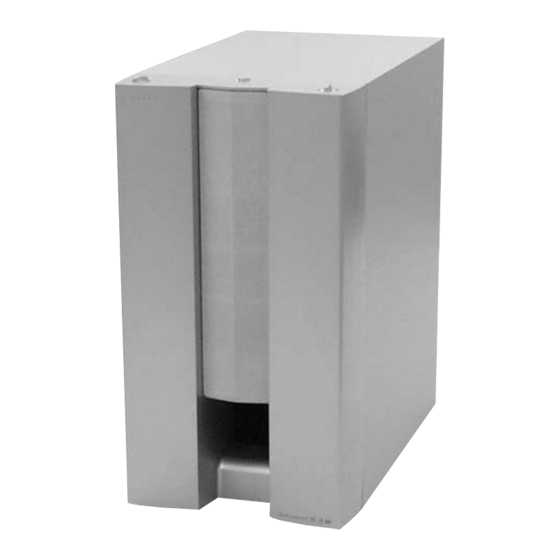
Active Subwoofer (SA-WMS325)
Center Speaker (SS-CN325)
Front and Rear Speakers (SS-V325)
SS-V325 (front and rear speakers)
Speaker system
Full range,
magnetically shielded
5.5 × 11 cm (
Speaker units
in.), cone type
Enclosure type
Bass reflex
Rated impedance
8 ohms
Power handling capacity
Maximum input power:
100 watts
Sensitivity level
87 dB (1 W, 1 m)
Frequency range
90 Hz - 20,000 Hz
Approx. 70 × 152 × 126
Dimensions (w/h/d)
7
mm (2
/
8
including front grille
Mass
Approx. 830 g (18 lb 5
oz) each
SS-CN325 (center speaker)
Full range × 2,
Speaker system
magnetically shielded
5.5 × 11 cm (
Speaker units
in.), cone type
Enclosure type
Bass reflex
Rated impedance
8 ohms
Power handling capacity
Maximum input power:
120 watts
Sensitivity level
89 dB (1 W, 1 m)
Frequency range
90 Hz - 20,000 Hz
Dimensions (w/h/d)
Approx. 300 78
126 mm (11
5 in.), including front
grille
Mass
Approx. 1600 g (35 lb 4
oz)
Sony Corporation
9-929-572-12
2001G0500-1
Home Audio Company
C 2001.7
Shinagawa Tec Service Manual Production Group
SA-VE322/VE325/WMS325/
SA-WMS325
SS-V325
SA-VE322
SA-VE325
a
–
a
SPECIFICATIONS
SA-WMS325 (subwoofer)
Speaker system
×
7
7
Speaker unit
/
/
32
16
Enclosure type
Reproduction frequency range
Amplifier section
Continuous RMS power output
× 6 × 5 in.),
Inputs
LINE IN (input pin jack)
SPEAKER IN (input terminals)
Outputs
LINE OUT (output pin jack)
SPEAKER OUT (output terminals)
×
7
/
7
/
32
16
General
Power requirements
North American model:
European model:
Other models:
Power consumptions
× 3
×
/
/
7
1
8
8
Dimensions (w/h/d)
Mass
SS-CN325/V325
SS-CN325
a
a
a
Active subwoofer,
magnetically shielded
Woofer: 16 cm (6
/
in.),
3
8
cone type
Advanced SAW type
28 Hz - 200 Hz
75 W (8 ohms, 20 Hz -
20 kHz, 0.8% THD)
120 V AC, 60 Hz
220 - 230 V AC, 50/60 Hz
110 - 120 V/220-240 V
AC, 50/60 Hz
70 W
1 W (standby mode)
Approx. 205 × 385 × 389
× 15
× 15
mm (8
1
/
1
/
3
/
8
4
4
in.), including front grille
Approx. 10.3 kg
(22 lb 11 oz)
MICRO SATELLITE SYSTEM
US Model
Canadian Model
E Model
Australian Model
Chinese Model
SA-VE325
AEP Model
UK Model
SA-VE322/VE325
Supplied accessories
SA-VE325
Foot pads (20)
Audio connecting cord (1)
Speaker connecting cords, 10 m (32 ft 9
Speaker connecting cords, 3.5 m (11 ft 6 in.) (3)
1
Speaker connecting cords, 2.5 m (8 ft 2
SA-VE322
Foot pads (8)
Audio connecting cord (1)
Speaker connecting cords, 3.5 m (11 ft 6 in.) (2)
Speaker connecting cords, 2.5 m (8 ft 2
1
Design and specifications are subject to change without
notice.
3
/
in.) (2)
4
/
in.) (2)
2
/
in.) (2)
2
Advertisement
Table of Contents

Related Manuals for Sony SS-V325


Summarization of Contents
Service Manual Overview
Product Specifications
Key specifications for the SA-VE322/VE325/WMS325/SS-CN325/V325 system.
Safety Procedures
Safety Check-out and Leakage Test
Procedures for ensuring set safety and performing AC leakage tests before release.
Safety-Related Component Warning
Critical safety warning about components marked with ▲.
Diagram Notes and Board Locations
Notes for Diagrams
Explains abbreviations, symbols, and conventions used in diagrams.
Circuit Boards Location
Identifies the physical location of main circuit boards within the SA-WMS325.
Main Board Printed Wiring Board
Main Board Semiconductor Location
Lists semiconductor components and their locations on the main board.
Control Section Printed Wiring Boards
Control Section Semiconductor Location
Lists semiconductor components and their locations on the control boards.
Power Section Printed Wiring Boards
Power Section Semiconductor Location
Lists semiconductor components and their locations on the power boards.
Speaker Exploded Views
SS-V325 Speaker Exploded View
Visual breakdown of the SS-V325 speaker assembly with part references.
SS-CN325 Speaker Exploded View
Visual breakdown of the SS-CN325 center speaker assembly with part references.
Electrical Parts List - Power and Control Boards
Auto Power Board Electrical Parts
List of electrical components for the auto power board.
Connector Board Electrical Parts
List of electrical components for the connector board.
Control Board Electrical Parts
List of electrical components for the control board.
Electrical Parts List - Main Board Components
Main Board Capacitors and ICs
Electrical parts list for capacitors and integrated circuits on the main board.
Main Board Resistors and Diodes
Electrical parts list for resistors and diodes on the main board.
Electrical Parts List - Main Board Resistors and Transistors
Main Board Resistor Details
Detailed list of resistors on the main board, including values and types.
Main Board Transistor Details
Detailed list of transistors on the main board, including part numbers.
Electrical Parts List - Mode, Power Switch, and Accessories
Mode and Power Switch Board Parts
List of components for the mode and power switch boards.
Hardware and Accessories List
List of hardware, accessories, and packing materials.
Need help?
Do you have a question about the SS-V325 and is the answer not in the manual?
Questions and answers