Sony SA-VE312 Service Manual
Sony micro satellite system service manual
Hide thumbs
Also See for SA-VE312:
- Operating instructions manual (60 pages) ,
- Service manual (19 pages) ,
- Service manual (13 pages)
Table of Contents
Advertisement
SERVICE MANUAL
Ver 1.0 2000.2
• The SA-VE312 system consists of one unit
of SA-WMS315 and two units of SS-V315.
• The SA-VE315 system consists of one unit
of SA-WMS315, one unit SS-CN315 and
four units of SS-V315.
AUDIO POWER SPECIFICATIONS
POWER OUTPUT AND TOTAL
HARMONIC DISTORTION :
with 8 Ω loads both channels driven, from 20 - 150 Hz; rated
75 W per channel minimum RMS power, with no more than
0.8% total harmonic distortion from 250 mW to rated output.
SS-V315 (f
ront and rear speakers)
Speaker system
Full range, magnetically shielded
× 10 cm (
2 × 4 in.), cone type
Speaker units
5
Enclosure type
Bass reflex
8 Ω
Rated impedance
Power handling capacity
Maximum input power: 100 W
Sensitivity level
87 dB (1W, 1m)
Frequency range
90 Hz - 20,000 Hz
Approx. 68 × 150 × 125 mm
Dimensions (w/h/d)
× 6 × 5 in.), including front
3
(2
/
4
grille
Mass
European model:
Approx. 640 g (1 lb 7 oz) each
Other model:
Approx. 740 g (1 lb 10 oz) each
SS-CN315 (center speaker)
× 2, magnetically
Full range
Speaker system
shielded
× 10 cm (
2 × 4 in.), cone type
Speaker units
5
Enclosure type
Bass reflex
8 Ω
Rated impedance
Power handling capacity
Maximum input power: 120 W
Sensitivity level
89 dB (1W, 1m)
Frequency range
90 Hz - 20,000 Hz
Approx. 301 × 68 × 125 mm
Dimensions (w/h/d)
× 2
× 5 in.), including front
(11
7
/
3
/
8
4
grille
Mass
European model:
Approx. 1.4 kg (3 lb 1 oz) each
Other model:
Approx. 1.5 kg (3 lb 5 oz) each
SA-VE312/VE315/WMS315/
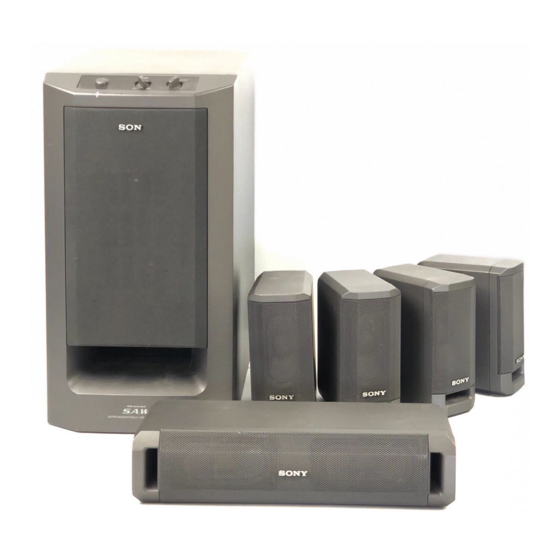
Photo: SS-V315
Photo: SA-WMS315
SPECIFICATIONS
SA-WMS315 (subwoofer)
System
Speaker system
Active subwoofer, magnetically
shielded
Speaker unit
Woofer : 16 cm (6
cone type
Enclosure type
Advanded SAW type
Continuous RMS power output
(8 Ω, 20 - 150 Hz, 0.8 % THD)
European model:
50 W
Other model:
75 W
Reproduction frequency range
28 Hz - 200 Hz
High frequency cut-off frequency
200 Hz
Inputs
LINE IN (input pin jack)
SPEAKER IN (input terminals)
Outputs
LINE OUT (output pin jack)
SPEAKER OUT (output terminals)
General
Power requirements
European model:
220 - 230 V AC, 50/60 Hz
Other model:
120 V AC, 60 Hz
Power consumptions
European model:
50 W
Other model:
70 W
Approx. 205 × 385 × 385 mm
Dimensions (w/h/d)
× 15
× 15
(8
1
/
1
/
8
4
front grille
Mass
Approx. 10.5 kg
(23 lb 2 oz)
SS-CN315/V315
Canadian Model
Australian Model
Photo: SS-CN315
Supplied accessories
SA-VE315
Foot pads (20)
Audio connecting cords (1)
3
/
in.),
8
Speaker connecting cords, 10 m (32 ft
Speaker connecting cords, 2.5 m (8 ft
SA-VE312
Foot pads (8)
Audio connecting cords (1)
Speaker connecting cords, 2.5 m (8 ft
Design and specifications are subject to change
without notice
1
/
in.), including
4
MICRO SATELLITE SYSTEM
US Model
AEP Model
UK Model
E Model
3
9
/
in.) (2)
4
1
2
/
in.) (5)
2
2
1
/
in.) (4)
2
Advertisement
Table of Contents

Related Manuals for Sony SA-VE312


Summary of Contents for Sony SA-VE312
- Page 1 AEP Model UK Model E Model Australian Model • The SA-VE312 system consists of one unit of SA-WMS315 and two units of SS-V315. • The SA-VE315 system consists of one unit of SA-WMS315, one unit SS-CN315 and four units of SS-V315.
-
Page 2: Safety Check-Out
Leakage current can be measured by any one of three methods. CRITIQUES POUR LA SÉCURITÉ DE FONCTIONNEMENT. NE REMPLACER CES COMPOSANTS QUE PAR DES PIÈSES SONY A commercial leakage tester, such as the Simpson 229 or RCA DONT LES NUMÉROS SONT DONNÉS DANS CE MANUEL OU WT-540A. -
Page 3: Diagrams
SECTION 1 DIAGRAMS 1-1. NOTE FOR PRINTED WIRING BOARDS AND SCHEMATIC DIAGRAMS • IC Block Diagrams IC302 uPC1237H Note on Printed Wiring Board: Note on Schematic Diagram: • X : parts extracted from the component side. • All capacitors are in µF unless otherwise noted. pF: µµF •... - Page 4 SA-VE312/VE315/WMS315/SS-CN315/V315 • See page 3 for IC block diagrams. 1-2. SCHEMATIC DIAGRAM (SA-WMS315) The components identified by Les composants identifiés par mark 0 or dotted line with mark une marque 0 sont critiques 0 are critical for safety. pour la sécurité.
-
Page 5: Printed Wiring Board
SA-VE312/VE315/WMS315/SS-CN315/V315 1-3. PRINTED WIRING BOARD (SA-WMS315) • See page 3 for Circuit Boards Location. • Semiconductor Location CONTROL BOARD Ref. No. Location D101 F-11 POWER BOARD D102 F-11 D103 F-11 D104 F-11 LED BOARD D301 D302 D303 D304 D501 D502... -
Page 6: Section 2 Exploded Views
SECTION 2 EXPLODED VIEWS NOTE: 2-2. SA-WMS315 (2) • -XX, -X mean standardized parts, so they may • Hardware (# mark) list and accessories and The components identified by mark 0 or have some differences from the original one. packing materials are given in the last of this dotted line with mark 0 are critical for safety. -
Page 7: Ss-Cn315 Parts
2-3. SS-CN315 not supplied @ @ @ not supplied @ @ @ Ref. No. Part No. Description Remarks Ref. No. Part No. Description Remarks X-4952-576-1 GRILLE (CN) ASSY, FRONT 4-226-378-01 PANEL (CN), FRONT 3-703-564-31 SCREW (3.5) 4-226-531-01 SCREW (3.5 X 62), +P TAPPING X-4952-577-1 CABINET (CN) ASSY 1-529-596-11 SPEAKER (5X10cm) 1-694-516-11 TERMINAL, SPEAKER... -
Page 8: Ss-V315 Parts
2-4. SS-V315 not supplied Ref. No. Part No. Description Remarks Ref. No. Part No. Description Remarks X-4952-570-1 GRILLE (SR) ASSY, FRONT 4-226-307-01 PANEL (SR), FRONT 3-703-564-31 SCREW (3.5) 4-226-531-01 SCREW (3.5 X 62), +P TAPPING X-4952-571-1 CABINET (SR) ASSY 1-529-595-11 SPEAKER (5X10cm) 1-694-516-11 TERMINAL, SPEAKER... -
Page 9: Electrical Parts List
SECTION 3 CONTROL MAIN ELECTRICAL PARTS LIST NOTE: • Due to standardization, replacements in the • RESISTORS • SEMICONDUCTORS parts list may be different from the parts All resistors are in ohms. In each case, u: µ, for example: specified in the diagrams or the components METAL: metal-film resistor uA...: µA... -
Page 10: Power Board
MAIN POWER Ref. No. Part No. Description Remarks Ref. No. Part No. Description Remarks C511 1-136-165-00 MYLAR 0.1uF 5.00% 50V R116 1-247-843-11 CARBON 3.3K 1/4W C512 1-136-165-00 MYLAR 0.1uF 5.00% 50V R117 1-249-424-11 CARBON 3.9K 1/4W F R118 1-249-436-11 CARBON 1/4W <... -
Page 11: Power Switch
POWER POWER SWITCH Ref. No. Part No. Description Remarks Ref. No. Part No. Description Remarks < TRANSISTOR > ACCESSORIES & PACKING MATERIALS ******************************* Q401 8-729-141-30 TRANSISTOR 2SC3623ATP-LK Q402 8-729-119-76 TRANSISTOR 2SA1115TP-EF 1-769-329-21 CORD, CONNECTION (PIN-PIN) Q403 8-749-010-25 IC MN2488-OPY-M 1-769-433-11 CORD, SPEAKER (WMS315) Q404 8-749-010-26 IC MP1620-OPY-M 1-769-433-21 CORD, SPEAKER... - Page 12 SA-VE312/VE315/WMS315/SS-CN315/V315 Sony Corporation 9-929-075-11 2000B1685-1 Home Audio Division Company Printed in Japan © 2000.2 Published by Quality Assurance Dept.
Need help?
Do you have a question about the SA-VE312 and is the answer not in the manual?
Questions and answers