Advertisement

SERVICE MANUAL
Ver. 1.0 2017.05
• All the units included in the HT-RT4/RT40
(SA-WRT4/WRT40, SS-RT4/SRT4, remote
control) are required to confi rm the operation
of SA-WRT4/WRT40. Check in advance that
you have all the units.
Note:
Be sure to keep your PC used for service and
checking of this unit always updated with the
latest version of your anti-virus software.
In case a virus affected unit was found during
service, contact your Service Headquarters.
COMPONENT MODEL NAME
Bar Speaker (Speaker System)
Surround Speaker (Speaker System)
Subwoofer (Active Subwoofer)
• The service manual for SS-RT4/SRT4 has been issued separately.
Please refer to the service manual for information.
Amplifi er section
POWER OUTPUT (rated)
Front L + Front R:
35 W + 35 W (at 2.5 ohms, 1 kHz,
1% THD)
POWER OUTPUT (reference)
Front L/Front R/Surround L/
Surround R:
65 W (per channel at 2.5 ohms,
1 kHz)
Center:
170 W (at 4 ohms, 1 kHz)
Subwoofer:
170 W (at 4 ohms, 1 kHz)
Inputs
USB
ANALOG IN
TV IN (OPTICAL)
Output
HDMI OUT (ARC)
HDMI section
Connector
Type A (19pin)
USB section
(USB) port
Type A
BLUETOOTH section
Communication system
BLUETOOTH Specifi cation
version 4.2
Output
BLUETOOTH Specifi cation
Power Class 1
Maximum communication range
Line of sight approx. 25 m
1)
9-890-690-01
Sony Corporation
2017E81-1
©
2017.05
Published by Sony EMCS (Malaysia) PG Tec
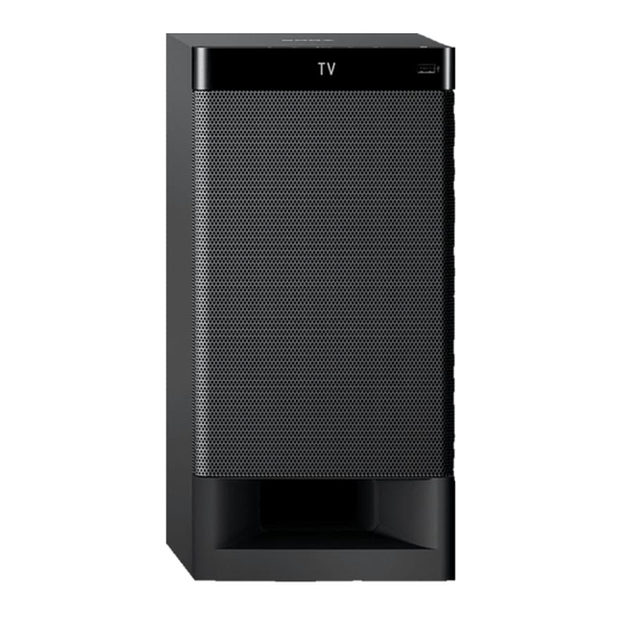
Photo: HT-RT4
HT-RT4
HT-RT40
SS-RT4
SS-RT4
SS-SRT4
SS-SRT4
SA-WRT4
SA-WRT40
SPECIFICATIONS
Frequency band
2.4 GHz band (2.4000 GHz –
2.4835 GHz)
Modulation method
FHSS (Freq Hopping Spread
Spectrum)
Compatible BLUETOOTH profi les
2)
A2DP 1.2 (Advanced Audio
Distribution Profi le)
AVRCP 1.6 (Audio Video Remote
Control Profi le)
Supported Codecs
3)
SBC
4)
, AAC
5)
Transmission range (A2DP)
20 Hz – 20,000 Hz (Sampling
frequency 32 kHz, 44.1 kHz,
48 kHz)
The actual range will vary depending
1)
on factors such as obstacles between
devices, magnetic fi elds around a
microwave oven, static electricity,
cordless phone, reception sensitivity,
antenna's performance, operating
system, software application, etc.
BLUETOOTH standard profi les
2)
indicate the purpose of BLUETOOTH
communication between devices.
3)
Codec: Audio signal compression and
conversion format
Subband Codec
4)
5)
Advanced Audio Coding
HT-RT4/RT40
Speaker section
Speaker system
Subwoofer system, Bass refl ex
Speaker
160 mm cone type
General
Power requirements
LA9 models only:
110 V - 240 V AC, 50/60 Hz
EA models only:
127 V – 240 V AC, 50/60 Hz
Except LA9, EA models:
220 V – 240 V AC, 50/60 Hz
Power consumption
On: 85 W
Standby: 0.5 W or less (Power
saving mode)
(When "CTRL" in "HDMI>" and
"BTSTB" in "BT >" are set to
"OFF")
Standby: 2.8 W or less
6)
(When "CTRL" in "HDMI>"
or "BTSTB" in "BT >" is set to
"ON")
Dimensions (w/h/d) (approx.)
190 mm × 392 mm × 315 mm
Mass (approx.)
7.8 kg
HOME THEATRE SYSTEM
ACTIVE SUBWOOFER
SA-WRT4/WRT40
AEP Model
UK Model
HT-RT4
E Model
Australian Model
HT-RT40
The system will automatically enter
6)
Power saving mode when there is
no HDMI connection and no BLUE-
TOOTH pairing history, regardless
of the settings you have made for
"CTRL" in "HDMI>" and "BTSTB"
in "BT >".
Supplied accessories
Remote control (1)
R03 (size AAA) batteries (2)
High Speed HDMI cable (1) (HT-RT40)
Optical digital cable (1) (HT-RT4)
Speaker bases (2)
Screws (8)
AC plug adaptor (1) (HT-RT40: LA9)
Design and specifi cations are subject to
change without notice.
HT-RT4/RT40
SA-WRT4/WRT40

Advertisement

Table of Contents
loading

Summary of Contents for Sony HT-RT4

  • Page 1 UK Model Ver. 1.0 2017.05 HT-RT4 E Model Australian Model • All the units included in the HT-RT4/RT40 (SA-WRT4/WRT40, SS-RT4/SRT4, remote HT-RT40 control) are required to confi rm the operation of SA-WRT4/WRT40. Check in advance that you have all the units.
  • Page 2 (6th generation) ® Bluetooth SIG, Inc. and any use of such marks by Sony Corporation is under iPod touch (5th generation) license. Other trademarks and trade names are those of their respective owners.
  • Page 3 COMPONENTS IDENTIFIED BY MARK 0 OR DOTTED LINE WITH MARK 0 ON THE SCHEMATIC DIAGRAMS AND IN THE PARTS LIST ARE CRITICAL TO SAFE OPERATION. REPLACE THESE COMPONENTS WITH SONY PARTS WHOSE PART NUMBERS APPEAR AS SHOWN IN THIS MANUAL OR IN SUPPLEMENTS PUBLISHED BY SONY.
  • Page 4: Table Of Contents

    HT-RT4/RT40 TABLE OF CONTENTS 5-4. Printed Wiring Boards - MAIN Board (RT4), ..........SERVICING NOTES EG4 MAIN Board (RT40) - ..........25 5-5. Printed Wiring Boards - EG4 OLED CHUKEI DISASSEMBLY PC Board - ..............26 2-1. Disassembly Flow ............
  • Page 5: Servicing Notes

    ADVANCE PREPARATION WHEN CONFIRMING OP- ERATION All the units included in the HT-RT4/RT40 (SA-WRT4/WRT40, SS- RT4/SRT4, remote control) are required to confi rm the operation of SA-WRT4/WRT40. Check in advance that you have all the units.
  • Page 6 HT-RT4/RT40 CAPACITOR ELECTRICAL DISCHARGE PROCESSING • Parts position When checking the board, for the electric shock prevention, con- 1. REGULATOR, SWITCHING 3L405W-4 board (Except nect the resistors to both ends of respective capacitor (C201 and E12) (page 6) C207) to discharge the capacitor (C201 and C207).
  • Page 7 HT-RT4/RT40 3. MAIN board (RT4) or EG4 MAIN board (RT40) MODEL IDENTIFICATION Distinguish by Part No. on the rear side of a main unit. – MAIN Board (RT4) or EG4 MAIN Board (RT40) – Rear View – (Component Side) –...
  • Page 8: Disassembly

    HT-RT4/RT40 SECTION 2 DISASSEMBLY • This set can be disassembled in the order shown below. 2-1. DISASSEMBLY FLOW 2-2. FRONT PANEL SECTION-1 (Page 9) 2-3. FRONT PANEL SECTION-2 (Page 10) 2-4. LOUDSPEAKER 16CM (Page 11) 2-5. CHASSIS SECTION (Page 12) 2-6.
  • Page 9: Front Panel Section-1

    HT-RT4/RT40 Note: Follow the disassembly procedure in the numerical order given. 2-2. FRONT PANEL SECTION-1 • Continued on next page. 1 Insert a jig in two notches of bottom of the unit, and lift the front panel section a little.
  • Page 10: Front Panel Section-2

    HT-RT4/RT40 2-3. FRONT PANEL SECTION-2 top side Fill in 2/3 of the bosses hole (step A to H) on the cabinet with new glue. Ensure the front panel section is fully inserted to cabinet. bosses hole glue 3 wire (flat type)
  • Page 11: Loudspeaker 16Cm

    HT-RT4/RT40 2-4. LOUDSPEAKER 16CM front side terminal (narrow side) terminal (wide side) loudspeaker 16cm terminal position 5 CN1001 (4P) loudspeaker 16cm 3 terminal (narrow side) 1 six screws ((1) (4 x 20), +BV TAPPING) 3 terminal – Front view –...
  • Page 12: Chassis Section

    HT-RT4/RT40 2-5. CHASSIS SECTION 3 Draw out chassis section in the arrow direction. 4 chassis section 2 panel, rear (EL-SW) – Rear view – 1 six screws (+BV TAPPING SCREW TYPE-1 3.5) 2-6. BLUETOOTH MODULE 4 two screws (+BVTP 3 X 8 TYPE2 IT-3)
  • Page 13: Speaker Chukei Pc Boar Board

    HT-RT4/RT40 2-7. SPEAKER CHUKEI PC BOAR BOARD 1 seven screws (+BVTP 3 X 8 TYPE2 IT-3) 3 Draw out wire (flat type) (18 core) from 4 chassis, top (EL-SW) chassis, top (EL-SW). top side rear side 7 one screw wire (flat type) (18 core)
  • Page 14: Main Board (Rt4), Eg4 Main Board (Rt40), Connector Board, Switching Regulator

    HT-RT4/RT40 2-8. MAIN BOARD (RT4), EG4 MAIN BOARD (RT40), CONNECTOR BOARD, SWITCHING REGULATOR 6 four screws (+BVTP 3 X 8 TYPE2 IT-3) 7 heat sink (EL-SW) Note: When installing the heat sink (EL-SW), spread the compound referring to "NOTE OF REPLACING THE IC1000 AND IC1002 ON THE MAIN BOARD (RT4)
  • Page 15: Test Mode

    → destination → MTK version → on the remote commander to exit this mode. Touch again the [ BT version → SW version (not available for HT-RT4/RT40 model) in this order, and returns to the model name display.
  • Page 16: Troubleshooting

    HT-RT4/RT40 SECTION 4 TROUBLESHOOTING 1. “PRTCT” is displayed on OLED display after turning the power on Note: Please remove USB (removable device) before troubleshooting. “PRTCT” is displayed on the OLED display after turning the power ON. “PRTCT” is displayed after...
  • Page 17 HT-RT4/RT40 3. The sound is not outputted Check the Subwoofer, Bar speaker (FRONT L, FRONT R, CENTER Replace the speaker which is not speakers) and Surround speaker functionable. (SUR L, SUR R speakers) are functionable. Check that the signal is inputted to...
  • Page 18 HT-RT4/RT40 4. Power is not turned on Power is not turned on. Reprogram serial flash IC2000 and check power on. The voltage of the following is 20V/32V SWITCHING REGULATOR: Replace the SWITCHING REGULATOR. Connector (CN101) pin 2 to 4 and 8.
  • Page 19 HT-RT4/RT40 5. USB cannot be detected USB cannot be detected. Refer to "Power is not turned Check IC3000 pin 4 is 3.3V. Check IC3000 pin 1 is 5.1V. on" on page 18. Replace complete MAIN Check that there is no Check coil (L3000) pin 1 and Check IC3000 pin 5 is 5.1V.
  • Page 20 HT-RT4/RT40 MEMO...
  • Page 21: Diagrams

    HT-RT4/RT40 SECTION 5 DIAGRAMS 5-1. BLOCK DIAGRAM - MAIN CONTROL Section - >001B AUDIO SECTION (Page 22) HT-RT4/RT40...
  • Page 22: Block Diagram - Audio Section

    HT-RT4/RT40 5-2. BLOCK DIAGRAM - AUDIO Section - STREAM PROCESSOR DIGITAL POWER AMP IC1001 IC1002 L1001 SUR L >001B DATA L R SL - – SDIN1 PWM P 7 47 INPUT A OUT A 39 DATA SL SR ONLY FOR SS-SRT4...
  • Page 23: Block Diagram - Power Supply Section

    HT-RT4/RT40 5-3. BLOCK DIAGRAM - POWER SUPPLY Section - SYSTEM PROCESSOR UNSW3.3V RESET IC2009 REMOTE CONTROL IC2001 RECEIVER IC5002 SWITCHING MTK RESET + 3.3V Q2003,Q2004 29 SIRCS +3.3V REG. BT 3.3V Q3209,Q3210 NFC MODULE (RC-S730 (WW)) PCONT BT DATA +3.3V REG.
  • Page 24 HT-RT4/RT40 THIS NOTE IS COMMON FOR PRINTED WIRING BOARDS AND SCHEMATIC DIAGRAMS. • Circuit Boards Location (In addition to this, the necessary note is printed in each block.) For Printed Wiring Boards. For Schematic Diagrams. BLUETOOTH module SPEAKER CHUKEI PC BOAR board...
  • Page 25: Eg4 Main Board (Rt40)

    HT-RT4/RT40 5-4. PRINTED WIRING BOARD - MAIN Board (RT4), EG4 MAIN Board (RT40) - • See page 24 for Circuit Boards Location. • : Uses unleaded solder. MAIN BOARD (RT4) / EG4 MAIN BOARD (RT40) (COMPONENT SIDE) REGULATOR, SWITCHING 3L405W-4 (EXCEPT E12) /...
  • Page 26: Printed Wiring Boards - Eg4 Oled Chukei Pc Board

    HT-RT4/RT40 5-5. PRINTED WIRING BOARD - EG4 OLED CHUKEI PC Board - 5-6. SCHEMATIC DIAGRAM - EG4 OLED CHUKEI PC Board - • See page 24 for Circuit Boards Location. • : Uses unleaded solder. • See page 31 for IC Block Diagrams.
  • Page 27: Printed Wiring Board - Touch Board

    HT-RT4/RT40 5-7. PRINTED WIRING BOARD - TOUCH Board - • See page 24 for Circuit Boards Location. • : Uses unleaded solder. TOUCH BOARD TOUCH BOARD (COMPONENT SIDE) (CONDUCTOR SIDE) JL4005 R4001 R4003 JL4003 IC4002 IC4001 JL4004 R4002 JL4002 VOL-...
  • Page 28: Printed Wiring Board - Speaker Chukei Pc Boar Board

    HT-RT4/RT40 5-9. PRINTED WIRING BOARD - SPEAKER CHUKEI PC BOAR Board - 5-10. SCHEMATIC DIAGRAM - SPEAKER CHUKEI PC BOAR Board - • See page 24 for Circuit Boards Location. • : Uses unleaded solder. JL6000 SPEAKER CHUKEI PC BOAR BOARD...
  • Page 29: Printed Wiring Board - Connector Board

    HT-RT4/RT40 5-11. PRINTED WIRING BOARD - CONNECTOR Board - 5-13. PRINTED WIRING BOARD - USB Board - • See page 24 for Circuit Boards Location. • : Uses unleaded solder. • See page 24 for Circuit Boards Location. • : Uses unleaded solder.
  • Page 30 HT-RT4/RT40 MEMO HT-RT4/RT40...
  • Page 31 HT-RT4/RT40 • IC Block Diagrams IC5002 SNM2140 (EG4 OLED CHUKEI PC BOARD) Noise & Gain Input Control Circuit Demo- AGC Amp Bandpass dulator GND_2 GND_1 IC4002 PST8429UL (TOUCH BOARD) GND 1 VREF – VDD 2 • IC Pin Function Descriptions TOUCH BOARD IC4001 CY8CMBR3108-LQXIT (TOUCH KEY CONTROLLER) Pin No.
  • Page 32: Exploded Views

    HT-RT4/RT40 SECTION 6 EXPLODED VIEWS Note: • -XX and -X mean standardized parts, so • Abbreviation The components identifi ed by mark 0 they may have some difference from the : Argentina model or dotted line with mark 0 are critical for original one.
  • Page 33: Chassis Section

    HT-RT4/RT40 6-2. CHASSIS SECTION MAIN board section When the BLUETOOTH MODULE is replaced, Note 1: refer to “NOTE OF REPLACING BLUETOOTH If wire (fl at type) is replaced, install it after bending Note 2: MODULE OR RC-S730 (WW)” on page 5.
  • Page 34: Main Board Section

    HT-RT4/RT40 6-3. MAIN BOARD SECTION SPEAKER CHUKEI PC CONNECTOR board (ns) BOAR board (ns) When the REGULATOR, SWITCHING 3L405W Note 2: board is replaced, spread the bond referring to “BOND FIXATION OF ELECTRIC PARTS” on page 6. If wire (fl at type) is replaced, install it after bending Note 3: it in the same form as that before replacement.
  • Page 35: Electrical Parts List

    HT-RT4/RT40 SECTION 7 ELECTRICAL PARTS LIST CONNECTOR EG4 MAIN MAIN EG4 OLED CHUKEI PC Note: When indicating parts by reference num- • Due to standardization, replacements in • CAPACITORS ber, please include the board name. the parts list may be different from the uF: μF...
  • Page 36 HT-RT4/RT40 SPEAKER CHUKEI PC BOAR TOUCH Ref. No. Part No. Description Remark Ref. No. Part No. Description Remark SPEAKER CHUKEI PC BOAR BOARD 4-533-400-11 SCREW +B 4X10 (WASHER) ***************************** 4-693-608-12 MANUAL, INSTRUCTION (ENGLISH) (UK, E3, SP, AUS, E12) 4-693-608-22 MANUAL, INSTRUCTION <...
  • Page 37 HT-RT4/RT40 MEMO...
  • Page 38 HT-RT4/RT40 REVISION HISTORY Ver. Date Description of Revision 2017.05 How to search for a contact point of signal lines or the like in DIAGRAMS SECTION If a contact point of a BLOCK DIAGRAM, PRINTED WIRING BOARD or SCHEMATIC DIAGRAM is shown in a different page, use the PDF fi...

This manual is also suitable for:

Ht-rt40Ss-rt4Ss-srt4Sa-wrt4

Table of Contents